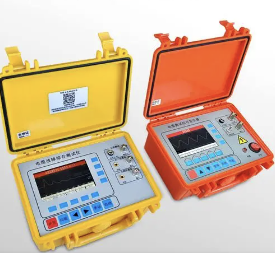

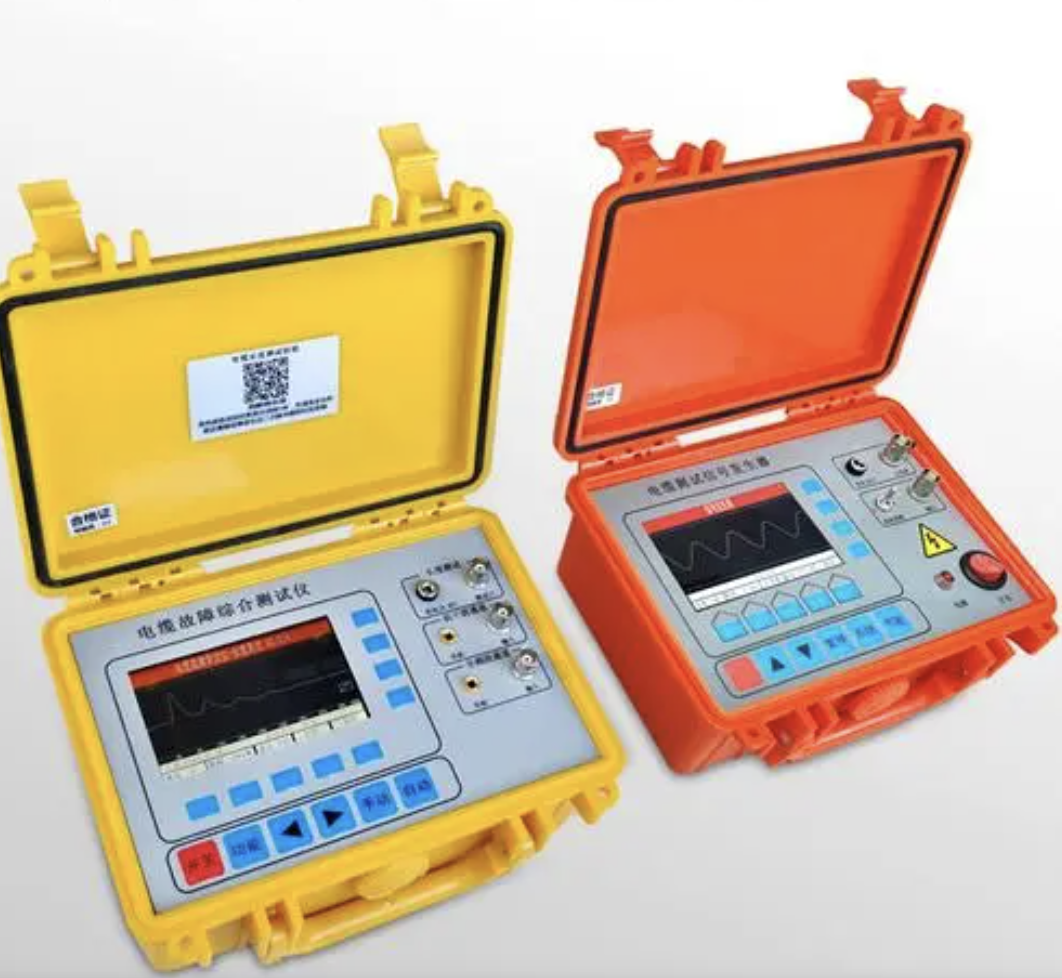
Transformer Turns Ratio Tester
The Transformer Turns Ratio Tester (abbreviated as "turns ratio tester", also known as "turns ratio and group tester") is a portable electronic testing instrument specifically used to accurately measure the turns ratio (ratio) of power transformer windings and the winding connection group (such as Yyn0, Dyn11, etc.). It is one of the core testing devices for transformer acceptance tests, preventive tests, and major overhaul inspections in the power system.
Working Principle
The core principle of a modern turns ratio tester is:
Signal Application: The instrument internally generates a known, stable low-voltage AC test signal (usually a sine wave, with a frequency that may differ from the power frequency to improve anti-interference capability), which is applied to the high-voltage side winding of the transformer.
Signal Measurement: Simultaneously, it accurately measures the high-voltage side voltage U₁ and the low-voltage side induced voltage U₂.
Ratio Calculation: The measured ratio Km = U₁ / U₂ is compared with the set theoretical value Kt to calculate the ratio error: Error (%) = [(Km - Kt) / Kt] × 100%
Group Determination: By measuring the voltage amplitude and phase difference between different winding terminals, the internal algorithm automatically determines the connection group number (1 to 12 o'clock).
Core Measurement Parameters
Ratio (K): The voltage ratio between the high-voltage side and the low-voltage side, reflecting whether the turns ratio of the windings is correct.
Ratio Error: The percentage deviation between the measured ratio and the theoretical ratio. According to the national standard GB1094, the allowable deviation for transformers with a voltage below 35kV and a ratio less than 3 is 0.5%.
Connection Group: The connection method and phase relationship of the high-voltage and low-voltage windings of the transformer (such as Dyn11, Yyn0, etc.).
Polarity: The relationship of the same-name terminals of the windings (additive polarity or subtractive polarity).
Main Functions and Features
Blind Test Function: Some advanced models are equipped with intelligent blind test algorithms, which can automatically identify and accurately measure the ratio and group without prior knowledge of the wiring group, making them suitable for testing old equipment and equipment without nameplates.
Ultra-wide Range: The ratio measurement range can reach 0.8 to 10000, covering from small distribution transformers to ultra-high-voltage large transformers.
Multi-category Testing: Supports ratio testing of three-phase transformers, single-phase transformers, PTs (voltage transformers), CTs (current transformers), Z-type connected transformers, and rectifier transformers.
Tap Position Testing: Supports verification of the ratio at up to 99 tap positions of the tap changer, confirming whether the switching is in place.
Soft Start/Stop: Smoothly outputs voltage to protect the test object from impact.
Automatic Range Switching: No need for manual adjustment; automatically matches the optimal range.
Data Storage and Printing: The built-in storage module can save dozens to thousands of data sets, supports USB export and thermal printing for on-site reports.
Typical Technical Parameters (using mainstream models as examples)
Table
Download as Table
Export as Image
Parameter Indicator
Ratio Range 0.8~10000
Accuracy ≤1000: ±0.1%; 1000~3000: ±0.2%; >3000: ±0.3%
Group Range 1~12 o'clock
Tap Positions Up to 99
Power Supply AC100~240V, 50/60Hz (built-in lithium battery version supports both AC and DC)
Operating Temperature -10℃~50℃
Relative Humidity <90%, no condensation
Instrument Weight Approximately 4.5~5kg
Typical Application Scenarios
Transformer Manufacturing Plants: Factory inspection (QC) to verify whether the actual ratio conforms to the design value and nameplate marking.
Power Companies: Installation acceptance, periodic preventive tests, and fault maintenance.
Parallel Operation Verification: Before multiple transformers are connected in parallel, it is necessary to ensure that the ratios are equal and the groups are the same; otherwise, huge circulating currents may damage the equipment.
Tap Changer Verification: To verify whether the ratio at each tap position of the on-load/off-load tap changer is correct and the contact is good.
Fault Diagnosis: Internal faults such as inter-turn short circuits and poor contact can cause abnormal ratios; even a small deviation may indicate a serious problem.