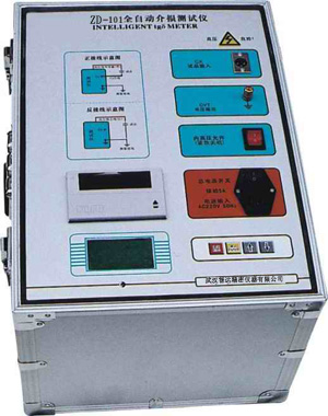

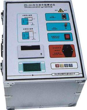
The dielectric loss tester (often referred to as the "dielectric loss tester") is a specialized precision instrument used in power systems to evaluate the insulation performance of high-voltage electrical equipment, and can be regarded as a "diagnostic expert" for the insulation condition of power equipment. It mainly prevents malignant power outage accidents by measuring key parameters without damaging the equipment.
Core Functions and Measurement Parameters
The core task of this instrument is to accurately measure the following two key parameters to judge the degree of deterioration of insulating materials:
Dielectric loss factor (tgδ): A physical quantity that characterizes the degree of energy loss of insulating materials under the action of an AC electric field. Pure and dry insulating materials have a very small tgδ value; when the insulation is damp, aged, cracked, or contains impurities, the energy loss increases and the tgδ value will significantly increase.
Capacitance (Cx): Reflects the overall condition of the insulating equipment. For example, internal moisture in the equipment will cause the capacitance value to increase; insulation aging and drying out or internal component breakdown and short circuit will cause the capacitance value to decrease.
⚙️ Working Principle and Anti-Interference Technology
In actual field tests such as in substations, there is often strong power frequency electromagnetic interference. Modern dielectric loss testers generally adopt the variable frequency anti-interference measurement method (heterodyne measurement method) to solve this problem.
Variable frequency technology: The instrument adjusts the test power supply frequency to deviate from the power frequency (such as 45Hz, 55Hz, or 47.5Hz, 52.5Hz, etc.), and performs measurement at non-power frequency, thereby effectively separating and avoiding 50Hz power frequency interference signals.
Digital processing: Through high-speed synchronous sampling and discrete Fourier transform (DFT) or digital correlation algorithms, the fundamental amplitude and phase difference of voltage and current are calculated, and then the tgδ value is accurately calculated.
Main Test Modes
According to the grounding method and structural characteristics of the tested equipment, the tester supports multiple wiring and measurement modes:
Positive connection method: Suitable for measuring test objects that are not grounded.
Reverse connection method: Suitable for measuring test objects that are directly grounded.
Self-excitation method: Specifically for special structural equipment such as capacitive voltage transformers (CVT), using its own intermediate transformer to excite and generate the test voltage, allowing the parameters of the main capacitor and the voltage-dividing capacitor to be measured at one time without an external high-voltage source.
🏭 Core Application Fields
The dielectric loss tester is widely used in power transmission and transformation systems and large industrial and mining enterprises, and is a core means to ensure the safe operation of the power grid. Its main detection objects include:
Capacitive equipment: Such as capacitive voltage transformers (CVT), high-voltage bushings, coupling capacitors, etc.
Transformer-type equipment: Such as power transformers (evaluating transformer oil and overall insulation), voltage transformers (PT), current transformers (CT), etc.
Other high-voltage equipment: High-voltage cables, generator stator windings, surge arresters, and dielectric loss measurement of insulating oil with a special oil cup.
Highly integrated: Modern fully automatic anti-interference dielectric loss testers are mostly integrated structures, with built-in standard capacitors, high-voltage step-up transformers, and microcomputer control systems, featuring simple operation and comprehensive safety protection functions such as overcurrent and overvoltage.
Temperature influence: The dielectric loss of insulating materials is greatly affected by temperature (usually increasing with temperature). Therefore, test results usually need to be converted to a standard temperature (such as 20°C) for comparison based on empirical formulas or manufacturer coefficients.
Environmental requirements: On-site testing should be carried out under good weather conditions, with an ambient temperature not lower than 5°C and relative humidity not greater than 80%. Before testing, the surface dirt of the equipment should be cleaned, and shielding measures should be taken when necessary to eliminate the influence of surface leakage current.