

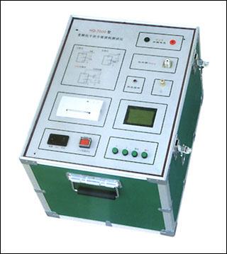
Transformer Turns Ratio Tester
The transformer turns ratio tester (also known as a turns ratio and vector group tester, or fully automatic turns ratio tester) is a specialized testing device used in power systems to accurately measure transformer winding turns ratio (ratio), connection group, polarity, and tap changer status. Its core function is to verify whether the actual transformer ratio is consistent with the nameplate design value, determine whether the windings have potential defects such as inter-turn short circuits or poor tap changer contact, and confirm whether the transformer meets the conditions for parallel operation.
I. Working Principle
The instrument operates based on the law of electromagnetic induction (K=N₁/N₂=U₁/U₂). An internal signal generator produces a low-voltage standard sine wave signal with stable frequency and known amplitude (usually using a different frequency such as 40Hz/60Hz to avoid 50Hz power frequency interference), which is applied to the high-voltage side winding of the transformer. High-precision voltage sensors synchronously collect the high-voltage side input voltage and the low-voltage side induced voltage, which are then converted into digital signals through filtering, amplification, and a high-precision analog-to-digital converter (ADC). The core control unit (microcontroller or ARM chip) performs Fourier analysis or RMS calculation on the digital signals to obtain the actual turns ratio, and compares it with the preset nominal ratio to calculate the error. Group determination is achieved by measuring the phase difference between line voltages or phase voltages on the high and low voltage sides, and automatically identifying groups 0-11 in combination with the winding connection method.
II. Mainstream Types and Selection Comparison
Type Application Scenario Core Advantages Precautions
Handheld/Portable On-site rapid inspection, daily maintenance of distribution transformers Lightweight (1-5kg), built-in lithium battery, easy to operate Relatively single function, limited anti-interference capability
General-purpose (Benchtop) Preventive testing of 35kV and below distribution transformers Cost-effective, comprehensive functions, supports three-phase automatic testing Moderate weight (5-8kg), requires external power supply
Professional (Three-phase Fully Automatic) 110kV and above power transformers, special transformers Strong anti-interference, supports blind testing, can test Z-type/rectifier transformers/Scott transformers Higher price, suitable for high-frequency professional testing
III. Core Points for Selection
Measurement accuracy (primary parameter): For ratio test accuracy, priority should be given to ±0.2% or above; for UHV scenarios, ±0.05% is required. Be sure to require the manufacturer to provide an accuracy calibration report issued by the National Institute of Metrology, and reject "verbal promises."
Range: The ratio measurement range must cover 1~10000, ensuring that both the highest and lowest ratio values of the transformer under test fall within the instrument's measurement range with margin. Too narrow a range will cause measurement data distortion or over-range alarms.
Anti-interference capability: Strong electromagnetic interference exists at substation sites, so equipment using different-frequency measurement technology (45Hz/55Hz and other non-power frequencies) or three-phase synchronous measurement technology should be selected to ensure stable data without drift.
Connection group testing capability: Not only check how many groups are supported (0-11 points), but also whether it has automatic group identification and "blind test" functions. For old transformers or equipment without nameplates, the blind test function can automatically identify the connection method and accurately calculate.
Special transformer adaptability: If special equipment such as electric furnace transformers, rectifier transformers, or Scott transformers is involved, be sure to confirm that the instrument menu explicitly includes test algorithms for such transformers; ordinary algorithms will produce huge phase errors.
Functional configuration: It should have functions such as data storage (≥100 groups), USB flash drive/Bluetooth export, on-site printing, and overcurrent/overvoltage/reverse connection protection. For outdoor work, choose models weighing ≤5kg, with protection rating IP54 or above, and with a built-in lithium battery.
Extended functions: Some high-end models support PT/CT ratio polarity testing, hexagonal diagram (vector diagram) display, excitation current measurement, etc. One machine with multiple functions can reduce procurement costs.
IV. Usage Method
Pre-test preparation: Strictly implement the process of power outage, voltage verification, and grounding wire installation, and confirm that both the high and low voltage sides of the transformer are completely de-energized and have no residual voltage. Check the transformer nameplate parameters (rated voltage, connection group, number of taps, etc.). Check that the instrument appearance is intact, calibration is valid, and test leads are not damaged.
Wiring operation:
Three-phase transformer: Connect the instrument high-voltage terminals A/B/C (yellow/green/red) to the transformer high-voltage side A/B/C, and the low-voltage terminals a/b/c to the transformer low-voltage side a/b/c. It is strictly forbidden to reverse high and low voltage.
Single-phase transformer: Connect instrument A/B to high-voltage side A/X, and a/b to low-voltage side a/x.
Three-winding transformer: Wire and test in sequence according to high-medium, high-low, and medium-low combinations; during each test, the third winding must be open-circuited.
The instrument grounding terminal must be reliably grounded.
Parameter setting: After power-on self-test passes, input rated high voltage/low voltage, rated ratio, total number of taps, tap spacing (such as 2.5%), and connection group (if unknown, select "automatic identification" or "blind test").
Test execution: Select the test mode (three-phase continuous/single-phase/two-winding/three-winding), and press the "Start" key to begin testing. The instrument automatically applies a low-voltage signal and measures; adjust the tap changer step by step, and save after the data stabilizes at each tap position. Before switching tap positions, you must first press the "Stop" or "Reset" key to cut off the test signal.
Result judgment: The allowable ratio error range at the rated tap position is ±0.5% (35kV and below) or ±0.25% (above 35kV); for transformers with voltage below 35kV and ratio less than 3, the allowable deviation is ±1%. The connection group and phase angle must be consistent with the nameplate.
Post-test operation: First turn off the instrument power, wait for automatic discharge to complete, then disconnect the test leads. Restore the transformer's original wiring and fill in the test record report.
V. Common Troubleshooting
No response after power-on Power not connected, fuse blown Check power cord and socket; replace fuse with same specification
Test data fluctuates greatly Poor wiring contact, strong electromagnetic interference, poor grounding Check wiring tightness; stay away from interference sources; ensure grounding resistance ≤4Ω
Displays "Err" or over-range High and low voltage reversed, test lead short circuit, incorrect standard ratio input Press reset key and check wiring; confirm standard ratio input does not exceed actual measured ratio by 10%
Incorrect group judgment Severe residual magnetism inside transformer, incorrect wiring phase sequence Retest after fully discharging the transformer; check phase sequence wiring
Abnormal output current Load short circuit, instrument protection activated Check whether test leads are short-circuited; restart instrument after troubleshooting
VI. Usage Precautions
Strictly prohibit live operation: It must be confirmed throughout that the transformer is in a de-energized state, and fully discharge before testing.
Wiring specifications: High-voltage side and low-voltage side leads must never be connected in reverse; unused lead clamps must be left floating, and short-circuiting or grounding is strictly prohibited.
Accurate parameter setting: Parameters such as rated ratio and tap spacing must be consistent with the nameplate; input errors will cause error calculation overflow.
Environmental requirements: The working environment temperature should preferably be -10℃~40℃, relative humidity ≤85%, and avoid strong electromagnetic field interference. When power supply interference is large, it is recommended to use an AC purified power supply with capacity greater than 200VA.
Maintenance: Regularly clean the instrument surface with a soft dry cloth; remove the battery when not in use for a long time; calibrate regularly (once a year is recommended).
As a core testing tool for transformer preventive testing, the transformer turns ratio tester requires comprehensive consideration of five dimensions during selection: measurement accuracy, range, anti-interference capability, group testing capability, and special transformer adaptability. If you have a specific application scenario (such as voltage level, transformer type, whether portability is needed), I can help you further refine the selection recommendations.