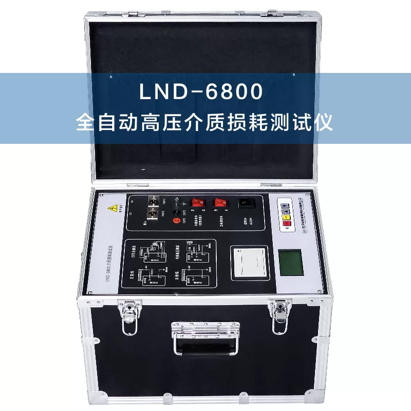

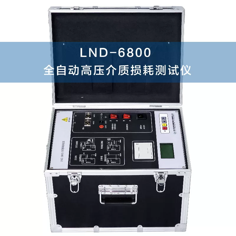
Loop Resistance Tester
A loop resistance tester (also known as a contact resistance tester or switch loop resistance tester) is a specialized high-precision instrument used to measure the contact resistance of conductive circuits in electrical equipment such as high-voltage switches, circuit breakers, disconnectors, and GIS combined appliances. It is a core tool for evaluating the quality of conductive circuit connections during handover acceptance and preventive tests in power systems.
Working Principle
The loop resistance tester employs the DC voltage drop method (four-wire method/Kelvin method) for measurement. The instrument injects a stable large DC constant current (typically 100A or 200A) into the circuit under test through a pair of current terminals (I+, I-), while simultaneously measuring the voltage drop across the test section with high precision through a separate pair of voltage terminals (V+, V-). It then automatically calculates and displays the resistance value based on Ohm's law (R=U/I).
The core advantage of the four-wire method lies in the separation of current and voltage measurement lines: since almost no current flows through the voltage sampling circuit, the resistance of the test leads themselves and contact resistance do not add to the measurement result. This effectively eliminates lead errors and achieves high-precision resistance measurements at the micro-ohm level.
The purpose of large current injection is to break through the oxide film and oil film on the contact surface, ensuring that the measurement result truly reflects the actual current-carrying contact state of the conductive circuit.
Key Technical Parameters
Table
Download as Table
Export as Image
Parameter Typical Range
Test Current 50A / 100A / 150A / 200A (multiple adjustable ranges), some models up to 400A~600A
Measurement Range 0~4mΩ (50A range), 0~2mΩ (100A range), 0~1mΩ (200A range)
Resolution 0.01μΩ
Accuracy Class 0.2 / 0.5 / 1.0
Power Supply AC 220V±10%, 50Hz
Display 320×240 or 800×480 high-definition LCD/touchscreen
Data Storage 200~1000 sets, supports power-off protection
Communication Interface RS232/RS485 (Modbus-RTU), USB, Bluetooth
Operating Temperature -10℃ ~ 50℃
Relative Humidity ≤90%RH
Weight Benchtop: approximately 3~6.5kg; handheld: approximately 1.35~1.6kg
Main Functions
Multiple Current Range Testing: Supports constant current output in multiple ranges from 50A to 200A, with automatic or manual selection of appropriate current based on the device under test
Automatic Range Switching: The instrument automatically identifies the resistance range of the measured object and switches to the optimal range without manual intervention
Temperature Compensation: Automatically converts measured values to a standard temperature (typically 20℃), eliminating the influence of ambient temperature on resistance values
Over-limit Alarm: Allows presetting an upper resistance limit; automatically alarms and determines pass/fail when measurement results exceed the limit
Long-duration Continuous Testing: Test time can be set from 0 to 9999 seconds, suitable for scenarios requiring long-term stable readings with power applied
Data Management: Built-in large-capacity memory, supports USB export to Excel files; some models support Bluetooth APP control and Word/Excel report generation
DC Constant Current Source Function: Can be used as a DC constant current source, supporting step-up current tests
Considerations for Choosing Between 100A and 200A
This is a common selection issue in engineering practice and should be understood from two levels:
Equipment Capability Level: Focus on whether the instrument can cover the current ranges required by the project, and confirm the duration, output stability, and protection logic for each range
Test Implementation Level: Set the current according to the technical documents of the device under test, applicable standards, and work instructions; it is not simply a matter of "the higher the current, the better"
The engineering value of 200A lies in: for low resistance values in the tens of micro-ohms, increasing the current doubles the voltage drop signal (e.g., 50μΩ produces a 5mV drop at 100A and 10mV at 200A), improving the signal-to-noise ratio and reading stability. However, test power is proportional to the square of the current (P=I²R), so the thermal load at 200A is four times that at 100A, requiring attention to contact temperature rise and terminal heating.
Safety Protection Mechanisms
Overheat Protection: Automatically reduces current or shuts down when internal temperature becomes too high during prolonged high-current output
Open Circuit Protection: Automatically cuts off output when the current loop is open, preventing high-voltage spikes
Short Circuit Protection: Automatically limits current when output is short-circuited
Ground Detection: Ensures reliable grounding of the test circuit
Typical Application Scenarios
High-Voltage Circuit Breakers: Measure the contact resistance of the main circuit after closing to detect defects such as contact erosion or insufficient pressure
Disconnectors: Measure contact resistance to evaluate the quality of conductive circuit connections
GIS Combined Appliances: Measure the contact resistance at conductive connection points in each bay
Busbar Connections: Measure the contact resistance at bolted connections of busbars
Cable Joints: Measure the conductive connection quality of cable terminations and intermediate joints
Weld Inspection: Evaluate the conductive performance of copper and aluminum busbar welds
Motor Windings: Measure winding DC resistance to detect inter-turn short circuits or loose connections
Applicable Standards
DL/T 845.4-2019: General Technical Specifications for Resistance Measuring Devices - Part 4: Loop Resistance Testers (current, replacing the 2004 version)
JJG 1052-2025: Verification Regulation for Loop Resistance Testers (effective from December 11, 2025, replacing the loop resistance tester section of JJG 1052-2009)
JJG 1205-2025: Verification Regulation for DC Resistance Testers (replacing the DC resistance tester section of JJG 1052-2009)
GB 50150-2016: Standard for Handover Test of Electrical Equipment Installation Engineering
DL/T 596-2021: Regulations for Preventive Tests of Electric Power Equipment
Key Points for Measurement Criteria
To determine whether loop resistance is abnormal, it is not advisable to simply apply a general rule of "below a certain fixed micro-ohm value." A more reliable approach is:
Establish a Baseline: Use factory values or handover test values as a reference, and compare subsequent periodic tests against this baseline
Longitudinal Trend: If historical data for the same device shows a continuous increase, attention should be paid even if the value has not exceeded the limit
Horizontal Comparison: If there are significant differences among the three phases, investigate the status of contact pressure, connectors, and flexible connections
Repeatability Verification: If repeated measurements of the same phase show large fluctuations, first confirm the wiring and instrument stability
Major Brands
Imported Brands: Megger (UK), DV Power, AEMC/Chauvin Arnoux (France), etc.