

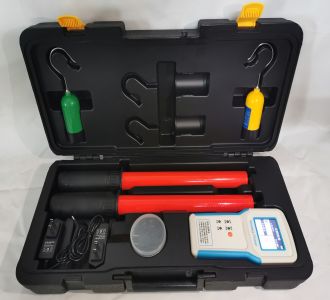
Loop Resistance Tester
The loop resistance tester (also known as a contact resistance tester or micro-ohmmeter) is a dedicated instrument used in power systems to measure the contact resistance of conductive loops such as high-voltage switches, circuit breakers, disconnectors, GIS equipment, and busbar connection points. Its core principle is the DC voltage drop method (four-wire Kelvin measurement), which breaks down the oxide film on contact surfaces by outputting a constant large current (usually ≥100A), accurately measuring micro-ohm level resistance values to evaluate the reliability of conductive connections.
Working Principle
The instrument's internal high-frequency switching power supply outputs a stable DC large current (I+, I-), which flows through the measured resistance Rx; meanwhile, an independent voltage sampling circuit (V+, V-) measures the voltage drop U across Rx. According to Ohm's law R=U/I, the instrument automatically calculates and displays the resistance value. The four-wire connection separates the current loop from the voltage measurement loop, effectively eliminating the influence of the test lead's own resistance and contact resistance on measurement results.
Key Selection Points
Test current (primary parameter): According to DL/T 845.4 and GB/T 11022 standards, the loop resistance test current for high-voltage switches shall not be less than 100A to effectively break down the oxide film on contacts.
Routine preventive testing (10kV-35kV switchgear, circuit breakers): Choose 100A standard models, which offer the greatest versatility.
GIS/GIL equipment, new switch acceptance testing, high-precision applications: Choose 200A and above, as larger current signals are stronger and have better anti-interference capability.
Large generator busbars, extra-long cable joints: Require 300A-600A or even larger currents.
Outdoor inspection, high-altitude work: Choose 100A handheld models (weight ≤3kg), but confirm that the current meets standards and anti-interference capability meets on-site requirements.
Measurement range and accuracy: Switch loop resistance is typically in the range of tens to hundreds of micro-ohms, and mainstream ranges of 0-1999μΩ or 0-2mΩ are sufficient. For routine maintenance, ±0.5% accuracy is adequate; for metrological calibration or scientific research, ±0.2% or Class 0.2 is required.
Anti-interference capability: Strong power-frequency electromagnetic interference exists at substation sites, so intelligent devices using high-frequency switching power supply technology and digital signal processing (DSP) technology should be preferred, with dedicated anti-power-frequency interference functions.
Four-terminal connection method: The instrument must support four-wire measurement, which is a basic standard requirement and a prerequisite for ensuring micro-ohm level measurement accuracy.
Structural forms:
Benchtop/split-type: High precision, full-featured, suitable for laboratories or fixed locations, weighing approximately 3-6.5kg.
Handheld/integrated: Portable and lightweight (approximately 1.2-1.7kg), with built-in lithium battery, suitable for frequent outdoor mobile operations, but anti-interference capability and accuracy must be confirmed.
Functional configuration: Should include data storage (≥500 sets), USB/Bluetooth export, on-site printing, temperature compensation, overcurrent/overvoltage/back-EMF protection, and other functions.
Usage Instructions
Pre-test preparation: Confirm that the equipment under test is completely de-energized, voltage-verified, and fully discharged, and hang warning signs; check that the instrument's battery/power supply is normal and test leads are intact without damage; clean the contacts under test with sandpaper or alcohol to remove oxide layers and dirt.
Four-wire connection: Connect the current leads (I+, I-, thick wires) to the outside of the test point, and the voltage leads (V+, V-, thin wires) to the inside of the current leads (close to the test point, approximately 2cm apart); ensure test clamps make good contact and are tightly clamped; the instrument's protective ground wire must be reliably grounded.
Parameter setting and testing: Connect AC220V power, select test current after powering on (usually 100A); set test time (generally 10s-60s, or wait for the value to stabilize for more than 5 seconds); press the test button, and the instrument will automatically output current and display the resistance value; it is recommended to repeat the test 2-3 times and take the average.
After testing: First stop the test, turn off the output, then disconnect the test leads; remove temporary grounding wires and restore the equipment's original wiring; save or print the test data.
No response when powered on, LCD screen shows nothing 220V power not connected, fuse blown Check power cord and outlet; check and replace fuse (for 100A instruments, fuse not less than 6A)
No current during testing, resistance shows "1" (over-range) Current loop not properly connected, test switch not closed, switch under test not closed Check test lead connections and re-clamp; confirm the switch under test is in the closed position
Current is normal, resistance shows "1" or is obviously too large Voltage lead position incorrect (not connected on the inside), voltage lead open circuit, measured resistance over-range, contact oxidation Check whether voltage leads are connected inside the current leads; clean contacts; use a multimeter to measure P1, P2 voltage values and manually calculate for verification
Output current far less than rated value (e.g., less than 100A) Power supply voltage too low, power cord too thin or too long, C1/C2 terminals loose, poor contact Use qualified power supply and sufficiently thick and short power cords; tighten terminal posts; eliminate poor contact
Test data fluctuating and unstable Loose connections, oxidized test points, external electromagnetic interference, test leads coiled up Check clamp contact status; clean test points; spread out test leads, keep away from interference sources
Precautions for Use
Strictly prohibited to operate with power on: Must confirm the equipment is in a de-energized state throughout; operators must wear insulating gloves, insulating shoes, and other protective equipment.
Correct wiring sequence: When connecting, connect voltage leads first, then current leads; when disconnecting, reverse the order—disconnect current leads first, then voltage leads.
Burns prevention: During large current testing, test leads and connectors may heat up; strictly prohibited to touch exposed conductors or metal clamps during testing.
Test lead specifications: Users must not arbitrarily replace current leads; test leads should be as short and thick as possible, avoiding bending and tangling.
Maintenance: When not in use for extended periods, store in a ventilated and dry place, and protect from moisture; calibrate regularly (recommended annually) to ensure accuracy.
As a core detection tool for preventive testing of power equipment, the loop resistance tester requires comprehensive consideration of five dimensions during selection: test current, measurement accuracy, anti-interference capability, structural form, and functional configuration. If you have specific application scenarios (such as voltage level, equipment type, whether portability is needed), I can help you further refine the selection recommendations.