
High-voltage wireless phase detector
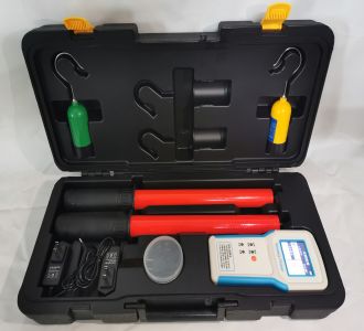
High-voltage wireless phase detector (also known as wireless phase detector, high-voltage voice phase detector) is a special live testing instrument used in the power system for phase verification and phase sequence verification of high-voltage power lines and substations. It is mainly used to detect whether the power supplies on both sides of the circuit breaker at the closing point of a ring network or dual-power grid are in phase, to prevent short circuits or equipment damage caused by inconsistent phase sequences.
⚙️ Core Components and Working Principle
The instrument system usually consists of two high-voltage detectors (acquisition terminals) and a receiving host, and some models are also equipped with insulated telescopic rods.
Signal Acquisition: The detector obtains voltage signals from high-voltage conductors through high-voltage capacitive voltage division or non-contact electric field induction principles, and processes them with filtering, amplification, etc.
Wireless Transmission: The detector sends phase information with precise timestamps to the receiving host via radio waves (such as 315MHz, 433MHz frequency bands).
Comparison and Display: After receiving the signals, the host aligns the waveforms based on timestamps, calculates the phase difference angle between the two voltage signals in real time, and displays the result of "in phase" or "out of phase" on the screen or via voice broadcast.
Main Functions and Technical Features
Multi-function Integration: In addition to the core phase verification function, it also has functions such as voltage detection, phase sequence measurement (positive/reverse phase sequence), frequency measurement, and voltage level display.
Cross Voltage Level Measurement: Supports automatic phase verification across a wide range of voltage levels from 0.38kV (low voltage) to 500kV (ultra-high voltage).
Contact and Non-contact Phase Verification:
Contact Type: Suitable for bare conductors of 35kV and below, or conductors with insulating sheath below 110kV.
Non-contact Type: Suitable for bare conductors above 35kV. The detector can complete phase verification by approaching the conductor and sensing the electric field, without direct contact, greatly improving safety.
Intelligent Voice and Display: Equipped with a color LCD screen, displaying phase angle, frequency, vector diagram, etc. on the same screen; supports real-person voice broadcast of test results, making operation intuitive.
Long-distance and Satellite Timing:
Ordinary Wireless Mode: The line-of-sight transmission distance is usually about 100 to 200 meters, and can be used through walls.
Satellite Timing Mode: Built-in multi-mode satellite timing modules such as GPS/BeiDou achieve microsecond/nanosecond level time synchronization, extending the phase verification distance to 500km or even more than 800km, suitable for remote grid interconnection.
Key Technical Parameters Reference
Specific parameters vary by model; the following are typical industry technical indicator ranges:
Table
Download as table
Export as image
Parameter Item Typical Value/Range
Phase Verification Voltage Range 0.38kV ~ 500kV
Phase Difference Accuracy Error ≤ 5° or ≤ 10°
In/Out of Phase Judgment Standard Phase difference ≤ 15° or < 30° is judged as in phase; > 30° is judged as out of phase
Wireless Transmission Distance Line-of-sight 100m ~ 200m (satellite timing can reach hundreds of kilometers)
Working Environment Temperature -35℃ ~ +50℃
High-voltage Leakage Current <10μA
Safety Matters and Operating Specifications
High-voltage wireless phase detector is a live testing tool. During operation, the "Safety Work Regulations for Electric Power" must be strictly followed:
Insulation Inspection: Before use, the integrity of the insulated telescopic rod must be checked, and the insulating rod must undergo regular withstand voltage tests (note: the built-in antenna part of the insulating rod cannot undergo withstand voltage tests).
Safety Distance: During on-site testing, operators must maintain the high-voltage safety distance specified by the power department.
Non-contact Operation: When performing phase verification on lines of ≥66kV (or above 35kV), non-contact inductive phase verification must be used, and direct contact with high-voltage bare conductors is strictly prohibited.
Standard Wiring: Ensure that the detector is firmly connected to the insulating rod, and the test clamp has good contact; in strong electric field environments, the instrument will usually automatically alarm.
Data Management: Save data promptly after testing. If not used for a long time, remove batteries or charge regularly, and store the instrument in a dry environment without high temperature and dust.