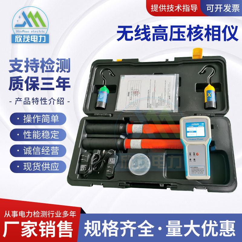

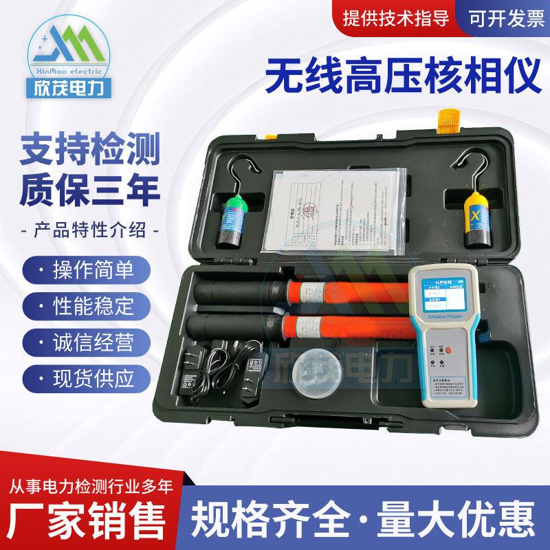
High-voltage wireless phase verification instrument
High-voltage wireless phase verification instrument (also known as wireless phase verifier, high-voltage voice phase verifier) is a special safety tool used for phase verification and phase sequence verification under live conditions in power lines and substations. It realizes real-time comparison of phase signals from two or more high-voltage collection points through wireless transmission technology, and is the core equipment to ensure correct phase sequence in grid interconnection, loop network renovation, and line maintenance.
Working principle
The high-voltage wireless phase verification instrument consists of two transmitters (collectors/detectors) and one receiver (host). The working process is as follows:
Signal acquisition: Two collectors respectively obtain voltage phase signals from the high-voltage conductor under test through contact (hanging on the conductor) or non-contact (electromagnetic induction) methods.
Wireless transmission: The collector sends the processed phase signal to the host via wireless radio frequency (315MHz/433MHz/2.4G frequency hopping, etc.).
Phase comparison: After receiving the two signals, the host calculates the phase difference angle between the two voltage groups and automatically determines whether they are in phase or out of phase.
Result output: The phase difference value and vector diagram are displayed on the LCD screen, and voice prompts "Same phase" or "Caution, phase different" are given.
Long-distance phase verification adopts GPS/Beidou satellite timing technology: The internal clocks of each collector are synchronized with UTC time (error in microseconds to nanoseconds), and each independently records phase data with precise timestamps. The host aligns waveforms through timestamps and calculates the phase difference, enabling remote phase comparison of ≥500km.
Core functions
Phase verification: Determine whether two lines or two power sources are in the same phase, preventing short circuit accidents caused by phase sequence errors during grid interconnection.
Voltage detection: Detect whether the line is live, replacing the traditional voltage detector function.
Phase sequence measurement: Determine whether the phase sequence of A/B/C three phases is positive or negative.
Frequency measurement: Real-time display of grid frequency (45Hz~65Hz range).
Transformer group analysis: Some models support determination of transformer connection group.
Key technical parameters
Table
Download as table
Export as image
Parameter Typical range
Phase verification voltage range 10V ~ 500kV (some models 5V~220kV)
Phase range 0° ~ 360°
Phase difference accuracy ≤5° (some models self-calibration error ≤±3°)
Frequency accuracy ±0.1Hz
Frequency range 45.0Hz ~ 65.0Hz
Wireless transmission distance Line-of-sight 100m~200m (short distance), ≥500km (GPS remote)
Phase resolution 1°
Sampling rate 3 times/second
Insulating rod length Retracted state 600~670mm, extended state 3000~3200mm
Insulating rod voltage withstand level ≤110kV (standard rod), ≤220kV (extended rod)
High-voltage measurement leakage current <10μA
Data storage 200~1000 groups, supports USB upload
Power supply Rechargeable lithium battery
Operating temperature -35℃ ~ +50℃
Relative humidity ≤95%RH
Same phase/out of phase determination criteria
Same phase: Phase difference ≤15° (some models use ≤30° as the boundary), voice prompt "Same phase"
Out of phase: Phase difference ≈120° or 180° (or within 100°~140°, 220°~260° range), voice prompt "Caution, phase different"
Special case: When the connection groups of two lines are different, a fixed phase difference of 30° or 60° may occur, which needs to be judged in combination with group analysis.
Contact and non-contact phase verification
Depending on the voltage level, the phase verification method differs:
≤10kV: The collector can directly contact the conductor or insulation layer for phase verification.
≥66kV: Contact or non-contact methods can be used.
110kV~220kV: The collector is placed 300mm~1000mm below the conductor, collecting signals through electromagnetic induction.
500kV: The collector is placed 1000mm~2000mm below the conductor (allowable deviation of 300mm left and right).
Safety protection mechanisms
Non-contact measurement: High-voltage lines do not require direct contact with conductors, avoiding electric shock risk.
Insulating rod protection: Made of alkali-free glass fiber cloth + epoxy phenolic resin material, high insulation, moisture-proof, impact-resistant.
Voice prompt: The phase verification result can be obtained through sound from a distance without looking down at the screen.
EMC electromagnetic compatibility: Complies with electromagnetic compatibility standards, adapts to complex electromagnetic field interference environments.
Automatic shutdown: Automatically shuts down after 1 hour of no operation to save battery.
Typical application scenarios
Grid interconnection: Before commissioning of new substations or lines, verify the phase consistency of power sources on both sides.
Loop network phase verification: Six-phase synchronization detection for distribution equipment such as loop network cabinets and medium-voltage switchgear.
Line renovation: Verify phase sequence correctness after line reconnection or relocation.
Dual power supply switching: Confirm that the backup power supply is in phase with the main power supply.
Cross-station remote phase verification: Use GPS timing technology to compare the phase of two lines hundreds of kilometers apart.
Daily inspection: Live voltage detection, phase sequence confirmation.
Implementation standards
DL/T 971-2017: Portable phase verifiers for live working AC 1kV~35kV (current industry standard)
GB 13398-2008: Hollow insulating tubes, foam-filled insulating tubes, and solid insulating rods for live working
IEC 60855: Insulating rods and accessories for live working
Usage precautions
Personnel requirements: Operators must be trained in high-voltage operations and hold certificates. At least three people on site (two operators, one supervisor), and single-person operation is strictly prohibited.
Pre-use self-check: Check that the insulating rod is intact without cracks, battery is fully charged, X/Y collector signals are normal, and voltage detection must be performed before phase verification.
Environmental restrictions: Prohibited in rainy, foggy, humid weather and places with condensation; keep away from strong magnetic fields and large equipment.
Operating specifications: For 35kV and above, direct contact with bare conductors is strictly prohibited; non-contact inductive phase verification must be used. X/Y collectors cannot be mixed. Phase verification should be performed phase by phase (A to A, B to B, C to C).
Result confirmation: Must be double-confirmed by host display and voice prompt, not by experience. When the phase is incorrect, grid interconnection or closing is strictly prohibited.
Maintenance: The insulating rod must undergo voltage withstand test before first use and annually. Remove collector batteries if not used for a long time, and replace them at least once a year. Store in a dry and ventilated environment.
Key points to avoid pitfalls in selection
Accuracy verification: Require the manufacturer to provide third-party test reports, focusing on phase difference accuracy (should be ≤5°) and frequency accuracy (should be ±0.1Hz), and be wary of inflated parameters.
Voltage adaptation: Confirm that the voltage adaptation range covers the actual usage scenario, and prioritize models with "voltage adaptive recognition" function.
Transmission distance: Field test wireless transmission stability to ensure continuous signal and no data delay within the rated distance.
Insulation safety: Verify that the insulating rod material and voltage withstand level match the measured voltage, avoiding the risk of insulation breakdown from low-quality products.