

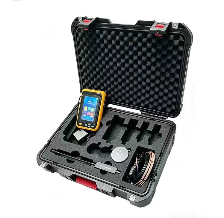
High-voltage Wireless Phase Verification Instrument
The high-voltage wireless phase verification instrument (also known as wireless phase verifier, high-voltage voice phase verifier) is a specialized instrument used for phase verification and phase sequence verification in power lines and substations. It achieves phase comparison of two high-voltage signals through wireless transmission technology, enabling phase verification without physical connections. It is a core safety device ensuring phase sequence consistency in grid interconnection, loop network transformation, and line maintenance. Working Principle
The high-voltage wireless phase verification instrument operates based on the synergy of electromagnetic induction and wireless transmission technology:
Signal Acquisition: Two detectors (X/Y collectors) are respectively positioned close to or in contact with the tested conductors via insulating rods, utilizing high-voltage capacitive voltage division or electric field induction principles to obtain voltage signals from high-voltage conductors.
Signal Processing and Transmission: The detectors filter, amplify, shape, and modulate the collected signals into wireless signals (commonly 315MHz, 433MHz, or 2.4G frequency hopping), which are then transmitted via antennas.
Signal Reception and Comparison: The host (receiver) simultaneously receives both signals, aligns the waveforms based on timestamps, and calculates the phase difference angle between the two voltage signals in real-time.
Result Determination: The host automatically provides audible, visual, and digital display results based on preset thresholds.
Long-distance Phase Verification: When the two measurement points are far apart (e.g., between different substations), GPS/Beidou satellite timing technology is used to achieve microsecond to nanosecond level time synchronization. Each detector independently stamps precise timestamps and wirelessly transmits them back, allowing the host to align and calculate the phase difference, enabling remote phase verification over distances ≥500km. System Composition
The equipment typically consists of the following components:
Detectors (Transmitters) ×2: Marked as X and Y respectively, installed at the top of insulating rods, responsible for collecting phase signals and transmitting wirelessly.
Receiver (Host) ×1: Equipped with an LCD screen, displaying phase difference, frequency, phase sequence, vector diagram, and phase verification results simultaneously.
Insulating Telescopic Rods ×2: Made of epoxy resin, with a contracted length of approximately 600mm and an extended length of approximately 3200mm, ensuring a safe distance for operators.
Accessories: USB communication cable, data upload software, charging devices, etc. Key Technical Parameters
Table
Download as Table
Export as Image
Parameter Typical Range
Phase Verification Voltage Range 10V ~ 550kV
Phase Measurement Range 0° ~ 360°
Phase Resolution 0.1° ~ 1°
Phase Difference Accuracy ≤±5° (High-precision type) / ≤±15° (Standard type)
Frequency Range 45Hz ~ 65Hz
Wireless Transmission Distance 100m ~ 200m (line of sight); Satellite mode ≥500km
Sampling Rate 2 ~ 3 times/second
Insulating Rod Withstand Voltage ≤110kV (extended) / ≤220kV (some models)
Data Storage 99 ~ 9999 sets
Operating Temperature -35℃ ~ +50℃
Protection Rating IP54 ~ IP65 Result Determination Criteria
Table
Download as Table
Export as Image
Determination Result Phase Difference Range Meaning
In-phase ≤±20° ~ ±30° Both measurement points are on the same phase; grid connection/closure is permissible.
Out-of-phase 90°~150° or 210°~270° Both measurement points are on different phases; grid connection is strictly prohibited.
The host typically provides dual confirmation via voice broadcast ("Phase identical"/"Caution, phase different") and screen display. Main Application Areas
Power Systems: Phase verification before grid connection of transmission lines, busbar phase verification in substations.
Distribution Networks: Six-phase synchronization detection in ring main units and medium-voltage switchgear, restoration of power supply after maintenance of 10kV/35kV lines.
New Energy: Phase sequence confirmation before grid connection of photovoltaic power stations and wind farms.
Railway/Metallurgy/Chemical Industry: Phase consistency verification of high-voltage power supply systems.
Transformer Connection Group Determination: Assisting in determining transformer connection groups. Phase Verification Methods
Depending on the voltage level, different phase verification methods are adopted:
Contact Phase Verification (≤35kV bare conductors / ≤110kV conductors with insulation sheath): The detector's metal probe hook directly contacts the conductor to collect signals.
Non-contact Phase Verification (>35kV bare conductors / >110kV lines): The detector is gradually brought close to the conductor, and the induced electric field signal is sufficient for phase verification, without direct contact, offering higher safety.
Ring Main Unit Phase Verification: Detectors must use dedicated probes and ring main unit test lines. Safety Operation Points
Personnel Requirements
Operators must undergo professional training and obtain high-voltage operation qualification certification.
On-site operations require at least three people (two operators, one supervisor); single-person operation is strictly prohibited.
Must wear insulating gloves, insulating shoes, and safety helmets.
Pre-use Inspection
Check that the instrument's appearance is intact and battery level is sufficient.
Insulating rods must be free of cracks and moisture, and within the validity period of withstand voltage tests.
Self-check must be performed to confirm that X/Y collectors are functioning properly.
Before phase verification, voltage detection must be conducted to confirm the line is energized.
Operational Specifications
Collectors must be securely attached to the line, without swaying, grounding, or short-circuiting.
X/Y collectors must not be interchanged, and must remain within the effective reception range of the host.
Verify phase by phase (A to A, B to B, C to C).
If data fluctuates or is unstable, stop immediately, eliminate interference, and retry.
Prohibited in rainy, foggy, humid conditions, and near strong magnetic fields.
Result Confirmation
Must rely on dual confirmation from the host display and voice prompt; do not judge based on experience alone.
If phase or phase sequence is incorrect, grid connection or closure is strictly prohibited.
Maintenance
Precision instruments must not be disassembled arbitrarily.
When not in use for extended periods, remove collector batteries and replace them at least once a year.
Insulating rods must undergo withstand voltage tests before first use and annually thereafter.
Store in a dry, ventilated environment, avoiding high temperature, humidity, and dust.
Applicable Standards
DL/T 971-2005: General technical conditions for portable phase verifiers for live working from 1kV to 35kV.
GB 13398-2008: General technical conditions for insulating rods for live working.
IEC 60855: Insulating rods for live working.
IEC 61243-1: Voltage detectors for live working.