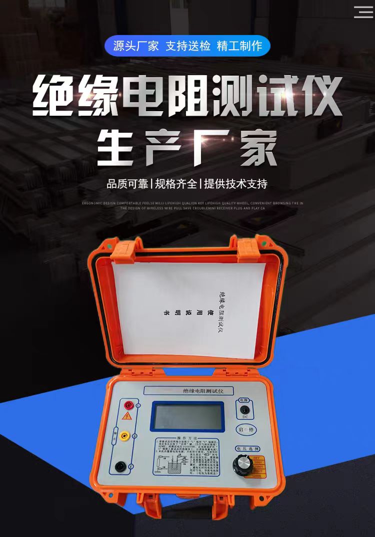

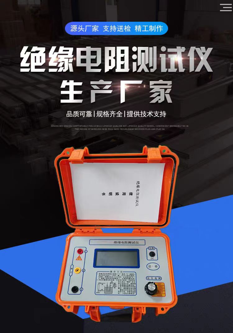
Insulation Resistance Tester
An insulation resistance tester, often referred to as a digital megohmmeter, insulation meter, or megger, is a professional instrument used to detect the insulation performance of power equipment, electrical circuits, and components. It applies a higher DC test voltage to the object under test, measures its tiny leakage current, and automatically calculates the insulation resistance value based on Ohm's law. It is a key tool for ensuring the safe operation of electrical systems.
The core principle of an insulation resistance tester is based on Ohm's law (R = V / I).
Applying high voltage: The instrument internally generates a constant DC high voltage (such as 500V, 1000V, 2500V, etc.) and applies it between the conductor of the device under test and ground (or the enclosure).
Measuring current: It measures the total current flowing through the insulating material. This current mainly consists of three parts:
Capacitive current: The current generated by charging the distributed capacitance of the insulator at the moment of testing, which decays extremely quickly.
Absorption current: Generated by the polarization process inside the insulating material, decaying slowly over time.
Leakage current: The conduction current that truly reflects defects such as impurities, moisture, or aging inside the insulating material, and is the key to evaluating insulation quality.
Calculating resistance: The instrument automatically calculates and displays the insulation resistance value (usually in MΩ or GΩ) based on the applied voltage and the measured stable leakage current.
Modern digital insulation resistance testers are feature-rich and go far beyond measuring a single resistance value:
Multiple test voltage levels: Provide multiple DC test voltage levels ranging from 50V to 15kV to meet the testing needs of equipment at different voltage levels.
Automatic calculation of diagnostic indicators:
Absorption Ratio (DAR): The ratio of the insulation resistance value at 60 seconds to that at 15 seconds, used to determine whether insulation is damp.
Polarization Index (PI): The ratio of the insulation resistance value at 10 minutes to that at 1 minute, a more reliable indicator for evaluating the aging or moisture condition of large-capacity equipment such as large motors and transformers.
Dielectric Discharge Rate (DD): Helps detect hard-to-find insulation problems such as delamination or cracking.
High short-circuit current: Typically 3mA to 10mA, which can quickly charge large-capacity devices under test (such as long cables or large transformers), shortening test waiting time and making readings stabilize faster.
Safety features:
Automatic discharge: After the test, automatically releases the residual high voltage on the device under test to protect operator safety.
Live circuit detection: Before starting the high voltage, automatically detects whether dangerous voltage exists in the circuit under test; if detected, it prohibits the test to prevent misoperation.
High voltage warning: Provides clear audible and visual warnings when outputting high voltage.
Data storage and connectivity: Supports storing multiple sets of test data and can export via USB or Bluetooth for report generation.
📈 Selection Guide
To choose the right insulation resistance tester, the following key factors should be comprehensively considered:
Table
Download as table
Export as image
Consideration Dimension Key Parameter/Function Selection Suggestion
Test Voltage Output voltage level Must match the rated voltage of the device under test. For example, choose 500V/1000V for low-voltage equipment, 2500V/5000V for medium-voltage equipment, and 10kV or above for high-voltage equipment.
Measurement Range Maximum insulation resistance value Choose based on equipment type. For ordinary appliances, a 10GΩ range is sufficient; for large motors, long cables, or high-voltage equipment, choose 100GΩ, 500GΩ, or even TΩ levels.
Diagnostic Functions PI, DAR, DD, etc. If you need to evaluate the insulation aging or moisture trend of large rotating machines, generators, transformers, etc., the Polarization Index (PI) function is essential.
Safety Rating CAT rating Ensure the instrument has a sufficient safety rating (such as CAT IV 600V) to handle possible transient overvoltages on site and ensure personal safety.
Application Scenario Portability, anti-interference For field or confined space work, prioritize handheld, battery-powered models with strong anti-interference capability.
Usage Precautions
Safety is the primary prerequisite for insulation testing, and operating procedures must be strictly followed:
Complete power-off: Before measurement, the device under test must be completely disconnected from all power sources and short-circuited to ground for discharge. Live operation is strictly prohibited.
Correct wiring:
L terminal (Line): Connect to the conductor part of the device under test.
E terminal (Earth): Connect to the enclosure or grounded part of the device under test.
G terminal (Guard): Connect to the shielding ring to eliminate the influence of surface leakage current on measurement results, especially important when measuring cables or insulation in humid environments.
Wait for stabilization: For large-capacity equipment, due to absorption and polarization processes, the insulation resistance reading will gradually rise over time. Wait for a sufficient time (such as 1 minute or 10 minutes) or until the reading stabilizes before recording, or let the instrument automatically calculate PI/DAR values.
Discharge after test: After the test, do not immediately touch the test leads or the device under test with your hands. Wait for the instrument to automatically discharge completely, or manually use a discharge rod to fully discharge the device under test.
Environmental recording: Insulation resistance values are significantly affected by temperature and humidity. Record the environmental conditions during the test to facilitate analysis and comparison of results. Common Misconceptions Clarified
Misconception: Can a multimeter's resistance range replace an insulation resistance tester?
Absolutely not. The output voltage of a multimeter's resistance range is usually only a few volts to a dozen volts, which cannot simulate the real working conditions of equipment under hundreds or thousands of volts. Many insulation defects that appear normal at low voltage (such as micro-cracks, moisture) will only be exposed and cause breakdown under high voltage. In addition, the resistance range of a multimeter (usually up to 20MΩ) is far from sufficient to measure qualified electrical insulation (usually above hundreds of megohms).
Misconception: Will the high voltage from insulation testing damage the equipment?
No. Insulation resistance testing is a non-destructive test. Its test voltage is lower than the equipment's withstand test voltage, and the output current is at the microampere/nanoampere level with extremely low energy, causing no damage to healthy insulation. Its purpose is precisely to detect potential insulation hazards before equipment is put into operation, preventing more serious short circuits, fires, or breakdown accidents during operation.