

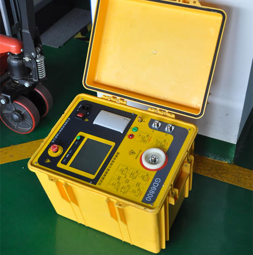
Insulation Resistance Tester
An insulation resistance tester (also known as a megohmmeter or high-resistance meter) is a precision electronic instrument specifically designed to measure the insulation resistance of electrical equipment, cables, and insulating materials. It is a core tool for preventive maintenance and safety hazard inspection of electrical equipment.
Working Principle
Based on Ohm's law, the instrument's internal circuit generates a stable DC high voltage (common ranges from 50V to 15kV), which is applied between the conductor under test and the enclosure (or ground). It measures the weak leakage current flowing through the insulator and automatically calculates and displays the insulation resistance value (typically in MΩ, GΩ, or TΩ).
In actual measurement, the leakage current consists of three parts:
Capacitive current: Generated at the instant of charging, disappears quickly
Absorption current: Generated by dielectric polarization, gradually decays
Leakage current: The steady-state current that truly reflects insulation quality
Terminals
Table
Download as Table
Export as Image
Terminal Name Connection Target
L Terminal Line Terminal Connect to the conductor under test (cable core, motor winding, etc.)
E Terminal Ground Terminal Connect to equipment metal enclosure, earth, or cable sheath/armor layer
G Terminal Shield Terminal Connect to shielding guard ring or insulation surface to eliminate surface leakage interference
📐 Key Technical Parameters
Table
Download as Table
Export as Image
Parameter Typical Range
Test Voltage 50V / 100V / 250V / 500V / 1000V / 2500V / 5000V / 10kV / 15kV
Measurement Range 0.01MΩ to 400GΩ (high-end models up to 35TΩ)
Accuracy ±1.5% reading to ±3% reading
Resolution 0.001MΩ in low-resistance range, 0.1GΩ in high-resistance range
High-Voltage Short-Circuit Current 3 to 8mA
Safety Rating CAT III 1000V / CAT IV 600V (compliant with IEC 61010 standard)
Protection Rating IP54 to IP65
Diagnostic Test Functions
In addition to basic insulation resistance measurement, professional insulation resistance testers also support the following diagnostic functions:
Dielectric Absorption Ratio (DAR): 60-second resistance value / 15-second resistance value, ≥1.3 is acceptable (motors/transformers/oil-paper insulated cables)
Polarization Index (PI): 10-minute resistance value / 1-minute resistance value, ≥2.0 is acceptable (large equipment)
Dielectric Discharge Rate (DD): Detects hard-to-detect insulation problems
Step Voltage Test (SV): Increases test voltage at a linear rate to identify potential hidden faults
Timed Test: Sets test duration and records the trend of insulation resistance over time
Pass/Fail Comparison: Sets thresholds for quick pass/fail determination
Test Voltage Selection Guide
Table
Download as Table
Export as Image
Equipment Under Test Recommended Test Voltage
Electrical equipment with rated voltage below 500V 500V or 1000V
Electrical equipment with rated voltage above 500V 1000V to 2500V
Low-voltage cables (≤1kV) 500V
Medium and high-voltage cables (6kV to 35kV) 2500V
High-voltage cables (≥110kV) 5000V or 10000V
Insulators 2500V to 5000V
Result Judgment Criteria
Low-voltage cables (380V): Minimum acceptable value ≥0.5MΩ
Motors: Insulation resistance between windings and between phase and enclosure ≥0.5MΩ; portable power tools ≥2MΩ; 1kV motors ≥1.0MΩ
Distribution cabinet busbars: ≥10MΩ
Abnormal judgment: A resistance value of 0 indicates a short circuit; 0.1 to 0.2MΩ indicates degraded insulation performance; a decrease of >30% compared to historical data requires troubleshooting
Temperature effect: For every 10°C increase in temperature, the resistance value approximately halves; ambient temperature should be recorded or conversion should be performed
Operating Procedures
Power-off confirmation: Cut off the power supply to the equipment under test and hang a warning sign
Full discharge: Short-circuit and ground the equipment under test for 3 to 5 minutes (5 to 10 minutes for high-voltage cables) to eliminate residual static charge
Clean connections: Wipe off dirt and moisture from the surface of the object under test, and disconnect connections to other circuits (such as PLCs and sensors)
Correct wiring: Connect the L terminal to the conductor, the E terminal to the enclosure or ground, and the G terminal to the shielding ring if needed
Start the test: Press the test button and hold for 10 to 60 seconds until the value stabilizes, then record it
Disconnect and discharge: First disconnect the L terminal wiring, then stop the test; immediately fully discharge the object under test (at least 2 minutes), and confirm there is no residual charge before disconnecting wires or touching
Safety points: Never measure with power on; do not touch test terminals by hand; outdoor measurement is prohibited when humidity >80% or during thunderstorms; high-voltage equipment measurement requires two-person operation (one person monitoring, one person testing).
🛒 Selection Recommendations
Table
Download as Table
Export as Image
Application Scenario Recommended Specifications
Insulation testing of low-voltage equipment (≤500V) Up to 1000V, range 10GΩ
Insulation testing of medium-voltage equipment Up to 2500V, range 500GΩ
High-voltage equipment (switchgear, generators, high-voltage cables) Up to 10kV, range 2TΩ
Ultra-high voltage/strong interference environments Up to 15kV, range 35TΩ, high noise suppression capability
Insulation + multimeter combined requirements Insulation multimeter type (integrated voltage, resistance, continuity functions)
Mainstream market brands include Megger (UK), Fluke (USA), KYORITSU (Japan), Hioki (Japan), Chauvin Arnoux (France), and domestic manufacturers, etc. Product forms include handheld, portable, and benchtop types.