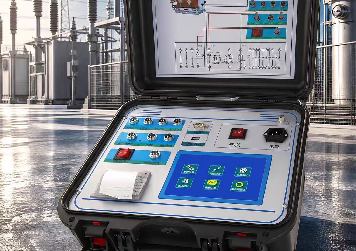

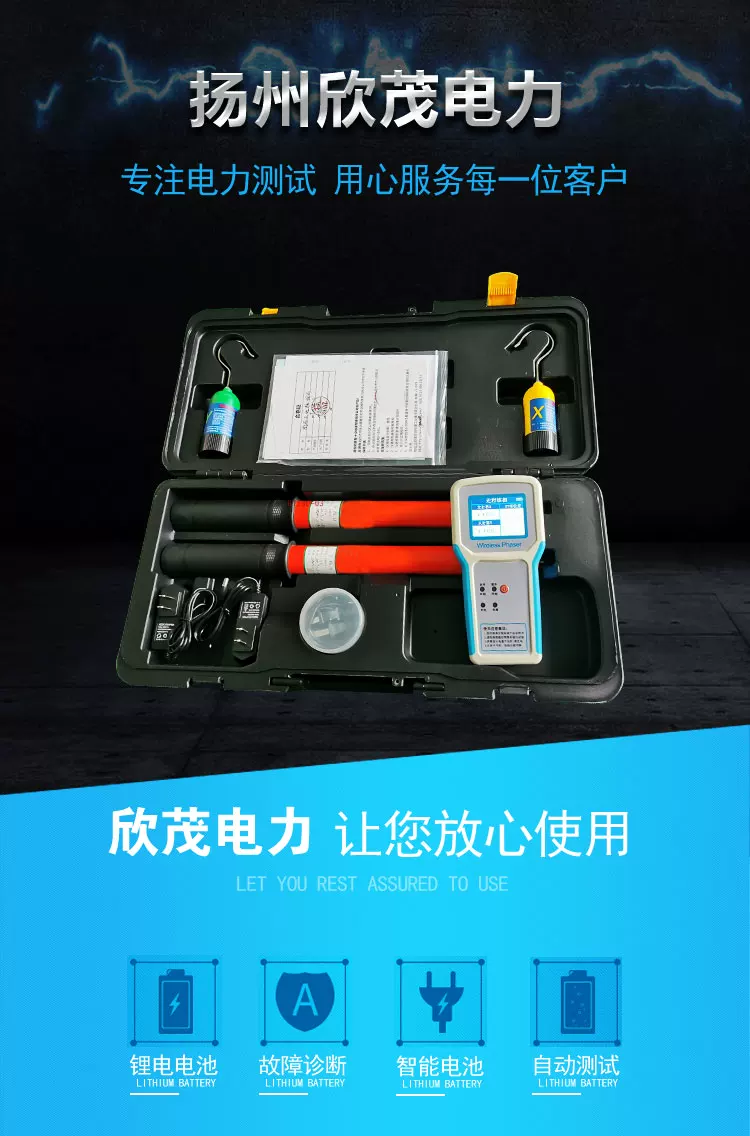
Insulation Resistance Tester
An insulation resistance tester (also known as a megohmmeter, digital摇表, or high-resistance meter) is a precision electronic instrument used to measure the insulation resistance of electrical equipment, lines, and materials. It evaluates insulation performance by applying a high DC voltage and measuring the weak leakage current, and is one of the core tools for preventive testing in power systems.
Working Principle
Based on Ohm's law, the instrument's internal circuit generates a high DC voltage (common ranges from 50V to 15kV), which is applied between the conductor under test and ground. It measures the resulting weak leakage current and, after calculation, directly displays the insulation resistance value in digital form (units: MΩ, GΩ, or TΩ).
Traditional hand-cranked megohmmeters generate high voltage by manually turning a generator, requiring the handle to be cranked at a steady 120 rpm, with readings indicated by a pointer. Modern digital models automatically generate high voltage via internal electronic circuits, offering simpler operation and higher accuracy.
Core Functions
Insulation resistance measurement: measures high-value insulation resistance, with ranges up to tens of TΩ
Dielectric Absorption Ratio (DAR): automatically calculates the 60-second/15-second resistance ratio to assess the degree of insulation moisture
Polarization Index (PI): automatically calculates the 10-minute/1-minute resistance ratio to assess insulation aging trends in large equipment
Dielectric Discharge (DD): evaluates the dielectric absorption characteristics of insulating materials
Step Voltage (SV)/Ramp Test: gradually increases voltage to detect weak points in insulation
Live Circuit Detection: automatically inhibits testing when a voltage greater than 30V is detected, protecting the operator
Automatic Discharge: automatically releases residual charge from the object under test after testing
Terminal Descriptions
Table
Download as Table
Export as Image
Terminal Name Connection Target
L Terminal Line Terminal Connects to the conductor under test (cable core, motor winding, etc.)
E Terminal Ground Terminal Connects to equipment enclosure, earth, or cable sheath/armor layer
G Terminal Shield Terminal Connects to the shield guard ring or insulation surface to eliminate surface leakage interference
Test Voltage 50V, 100V, 250V, 500V, 1000V, 2500V, 5000V, 10kV, 15kV
Measurement Range 0.01MΩ~35TΩ (depending on model)
Accuracy ±1.5%~±5% of reading
High-Voltage Short-Circuit Current 3~8mA
Safety Rating CAT III 1000V / CAT IV 600V
Protection Rating IP54~IP65
Operating Temperature -20℃~+55℃
Data Storage Supports USB/Bluetooth transmission
Test Voltage Selection Guide
Equipment Under Test Recommended Test Voltage
Electrical equipment with rated voltage below 500V 500V or 1000V
Electrical equipment with rated voltage above 500V 1000V~2500V
Low-voltage cables (≤1kV) 500V
Medium- and high-voltage cables (6kV~35kV) 2500V
High-voltage cables (≥110kV) 5000V or 10000V
Insulators 2500V~5000V
Result Judgment Criteria
Low-voltage cables (380V): acceptable lower limit ≥0.5MΩ
Low-voltage cables (normal temperature 20℃): insulation resistance should be ≥1MΩ
Motors: between windings, phase-to-phase, and phase-to-enclosure ≥0.5MΩ; portable power tools ≥2MΩ; 1kV motors ≥1.0MΩ
Distribution cabinet busbars: ≥10MΩ
Dielectric Absorption Ratio (DAR): 60-second resistance/15-second resistance ≥1.3 (motors/transformers/oil-paper insulated cables)
Polarization Index (PI): 10-minute resistance/1-minute resistance ≥2.0 (large equipment)
Abnormal judgment: a resistance of 0 indicates a short circuit; 0.1~0.2MΩ indicates reduced insulation performance; a decrease of >30% compared with historical data requires troubleshooting of hidden hazards
Operating Procedure
Pre-Test Preparation
Cut off power to the equipment under test and hang a warning sign
Short-circuit and ground the equipment under test to discharge for 3~5 minutes (5~10 minutes for high-voltage cables)
Wipe off dirt and moisture from the surface of the object under test, and disconnect it from other circuits
Place the megohmmeter horizontally and perform an open-circuit check (displays ∞) and a short-circuit check (displays 0)
Wiring and Testing
Connect the L terminal to the conductor, and the E terminal to the enclosure or ground (when measuring cables, connect the G terminal to the shield ring)
Press the test button and hold for 10~60 seconds until the value stabilizes, then record it
For hand-cranked models, crank steadily at 120 rpm and take the reading after 1 minute
Disconnecting and Discharging
Disconnect the L terminal wiring first, then stop the test
Immediately use a grounding rod or the instrument's discharge function to fully discharge the object under test (at least 2 minutes)
Only after confirming there is no residual charge may you disconnect wires or touch the object
Main Application Areas
Power systems: insulation testing of transformers, generators, high-voltage motors, and power cables
New energy: insulation performance verification of photovoltaic modules, wind power equipment, and energy storage batteries
Rail transit: preventive testing of traction motors and power supply lines
Industrial manufacturing: insulation condition assessment of switchgear, distribution cabinets, and capacitors
Building installation: acceptance testing of low-voltage lines and electrical equipment
Safety Precautions
Measuring with live power is strictly prohibited; before testing, you must confirm that the equipment is completely de-energized and fully discharged
Do not touch the test terminals by hand, and do not touch the equipment under test during testing
Outdoor measurement is prohibited when humidity is >80% or during thunderstorms
Insulation resistance is significantly affected by temperature; for every 10℃ increase in temperature, the resistance is approximately halved, so ambient temperature must be recorded or conversion performed
Test leads should be multi-strand flexible wires, and the two leads must never be twisted together
Measurement of high-voltage equipment requires two people: one to monitor and one to test