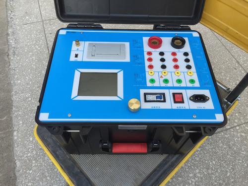

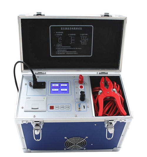
Cable Fault Tester
A cable fault tester is a comprehensive detection device specifically used for detecting and locating faults in power cables and communication cables. It can pinpoint the location and type of faults in the shortest possible time and is a core piece of equipment for power emergency repairs and cable maintenance.
Working Principle
The cable fault tester injects a test signal into the faulty cable and analyzes the propagation and reflection characteristics of the signal within the cable to determine the fault type and distance. Currently, three mainstream detection technologies are used:
Low-voltage pulse method (TDR/Time Domain Reflectometry): A low-voltage pulse is transmitted into the cable. The pulse generates a reflection at the fault point (where impedance changes abruptly). By analyzing the time difference between the reflected wave and the transmitted wave, combined with the cable's wave velocity, the fault distance is calculated. It is extremely effective for open-circuit and low-resistance faults, is simple to operate, and is currently the most mainstream detection method.
High-voltage flashover method (impulse flashover current method): A high-voltage pulse is applied to high-resistance faults, causing the fault point to break down and discharge. The fault location is determined by collecting the traveling wave signal generated by the discharge. It is suitable for high-resistance grounding and flashover-type faults.
Multiple pulse method: Complex high-resistance fault waveforms are converted into easily identifiable low-voltage short-circuit waveforms, greatly improving rough measurement accuracy. It is currently a standard technology in high-end equipment.
System Composition
A complete cable fault testing system usually consists of the following parts:
Test host (flash tester): Responsible for fault type determination and rough distance measurement, equipped with a large touchscreen, and supports waveform storage and playback
Cable route tracer and fault locator: Uses the principle of electromagnetic induction to detect cable route and burial depth, and to perform cable identification
Acoustic-magnetic synchronization pinpointing instrument: Precisely locates the geographic coordinates of the fault point by synchronously receiving the acoustic wave and electromagnetic wave signals generated by the discharge at the fault point
DC high-voltage generator: Provides impulse voltage for high-voltage flashover testing
Discharge sampler and pulse energy storage capacitor: Used in conjunction with the high-voltage flashover method
Dedicated test cables and accessories
📐 Key Technical Parameters
Table
Download as table
Export as image
Parameter Typical Range
Maximum test distance 20km~100km (up to 100km for open-wire lines)
Reading resolution 0.15m~1m
System error ≤±1%~±2%
Precise pinpointing error ≤±0.2m~±0.5m
Sampling frequency 6.25MHz~200MHz (adaptive or manual selection)
Detection blind zone 0~10m
Applicable voltage level 0~50kV
Impulse voltage Integrated type ≤15kV, split high-power type ≤35kV
Power supply mode AC 220V / DC 12V lithium battery, standby about 4~6 hours
Operating temperature -20℃~+50℃
Detectable Fault Types
Open circuit (broken wire): Cable conductor breakage
Short circuit: Short circuit between phases or between phase and ground
Low-resistance grounding: Fault with relatively low grounding resistance
High-resistance grounding: Relatively high grounding resistance, difficult for ordinary instruments to detect
High-resistance flashover: Intermittent fault that breaks down only under high voltage
Poor contact: Loose connection at conductor connection point
Leakage fault: Leakage current caused by slow insulation deterioration
Fault type determination: Use a multimeter or megohmmeter to preliminarily determine the nature of the fault (low resistance/high resistance/open circuit/flashover)
Rough measurement and location (distance measurement): Use the test host to transmit pulses or high-voltage flashover signals and read the fault distance
Path detection: Use a route tracer to determine the actual route and burial depth of the cable
Precise pinpointing: Use an acoustic-magnetic synchronization pinpointing instrument to search point by point on the ground and lock the exact location of the fault point
Excavation and repair: Excavate at the pinpointed location and carry out fault repair
Intelligent operation: Equipped with an industrial-grade touchscreen and a full Chinese menu, it can be used without professional training
Waveform analysis: Supports dual-trace display (comparison between fault waveform and normal waveform), waveform scale expansion, and dual-cursor automatic/manual positioning
Data storage and management: Built-in non-volatile storage, data is not lost when powered off; some devices support remote 3G/4G communication, allowing experts to remotely access and review waveforms in real time
Multifunctional integration: Some devices integrate the function of a route tracer, supporting pipeline route detection, burial depth measurement, and cable identification
Portable design: Handheld or case-type structure, suitable for outdoor field operations
Power system: Emergency repair of cable faults in urban distribution networks and substation incoming and outgoing lines
Industrial and mining enterprises: Maintenance of high- and low-voltage power cables
Rail transit: Troubleshooting of railway signal cables and subway power supply cables
Communications industry: Fault location for local telephone cables and high-frequency communication cables
Municipal engineering: Fault location for distribution cables in residential buildings and streetlight cables
Airports and oilfields: Detection of airport signal cables and special oilfield cables
DL/T 849.1~DL/T 849.3-2004: Technical standards for power cable fault testers
GB/T 16927.1-1997: High-voltage test technology standards
🛒 Selection Points
Clarify the type of cable under test: Power cable, communication cable, or control cable, voltage level, and length range
Test distance requirements: For municipal projects, 0~20km is generally sufficient; for long-distance transmission lines, a larger range should be selected
Positioning accuracy requirements: An error within ±0.5m is excellent and directly affects excavation efficiency
Fault type coverage: Ensure the equipment can cover complex fault types such as high-resistance flashover
Portability: For frequent outdoor operations, prioritize lightweight handheld designs
Completeness of accessories: Whether a full set of accessories such as a pinpointing instrument and route tracer is included, to avoid separate procurement