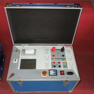

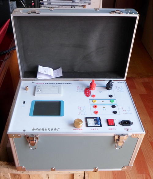
Transformer Tester Variable Frequency Comprehensive Transformer Tester
The Variable Frequency Comprehensive Transformer Tester you are interested in is a key device used for on-site testing of core parameters of current transformers (CT) and voltage transformers (PT) in power systems. It adopts advanced frequency conversion technology, solving the problems of bulky traditional power frequency test equipment and complex wiring, making it an essential instrument for field operations with installation (repair, test) qualifications.
⚡️ Core Working Principle and Technical Advantages
When testing CTs with high knee-point voltage using traditional power frequency methods, large voltage regulators and boosters are required, making on-site transportation and wiring extremely difficult. The core breakthrough of the Variable Frequency Comprehensive Transformer Tester lies in:
Variable Frequency Boost Technology: By outputting a non-power frequency (e.g., 45Hz/55Hz) excitation signal and utilizing the electromagnetic characteristics of the transformer itself, it only needs to output an AC voltage of 180V~250V to equivalently simulate a power frequency knee-point voltage as high as 60kV or even higher.
Lightweight and Portable: Since there is no need for external standard transformers, current boosters, high-current wires, or voltage regulation control boxes, the total weight of the device can usually be controlled within 10kg, allowing a single person to easily carry it to the site.
Strong Anti-Interference Capability: Using off-frequency testing effectively avoids on-site 50Hz power frequency electromagnetic interference, ensuring the accuracy of test data in strong electric field environments.
High Degree of Automation: One-click completion of all test items such as volt-ampere characteristics, ratio, polarity, DC resistance, burden, and error curves, with automatic calculation of knee-point, 10%/5% error curves, and other key parameters, and generation of test reports.
📊 Core Test Functions
A qualified Variable Frequency Comprehensive Transformer Tester should at least have the following functions:
Table
Download as Table
Export as Image
Test Object Core Test Items
Current Transformer (CT) Volt-ampere characteristics (excitation characteristics), ratio, polarity, secondary winding resistance, secondary actual burden, ratio error, phase error, 5%/10% error curves, core demagnetization
Voltage Transformer (PT) Volt-ampere characteristics (excitation characteristics), ratio, polarity, secondary winding resistance, secondary actual burden
Advanced Parameters (some models) Accuracy Limit Factor (ALF), Instrument Security Factor (FS), Secondary Time Constant (Ts), Remanence Factor (Kr), Saturated/Unsaturated Inductance, etc.
📋 Reference for Main Technical Parameters
When selecting a model, please pay attention to whether the following parameters meet your on-site needs:
Volt-ampere Characteristics Test
Output Voltage: 0~250V (RMS)
Output Current: 0~15A (RMS), peak up to 36A
Measurable Knee-point Voltage: up to 60kV (this is the core advantage of frequency conversion technology)
Ratio Test
CT Ratio Range: 1~40000 (or higher), accuracy ±0.1%
PT Ratio Range: 1~40000 (or higher), accuracy ±0.1%
Phase/Phase Error Test
Measurement Accuracy: ±5min or better, resolution 0.1min
Secondary Winding Resistance
Measurement Range: 0~300Ω, accuracy 1%±1mΩ
General Characteristics
Working Power Supply: AC 220V ±10%, 50Hz
Data Storage: ≥1000 groups, no data loss on power failure
Data Export: Supports USB export, can generate Word/Excel reports
Printing Function: Built-in micro thermal printer for on-site instant printing
Total Weight: < 10kg, easy for on-site transportation
🛡️ On-site Operation Safety and Specifications
Reliable Grounding: Before testing, the grounding terminal of the instrument must be reliably connected to the on-site grounding grid. This is the primary prerequisite for ensuring personal and equipment safety.
CT Secondary Side Must Not Be Open: During CT ratio, polarity, and DC resistance tests, ensure the CT secondary side circuit is complete. It is strictly forbidden to disconnect the secondary wiring during testing to avoid dangerous high voltage.
Wiring Confirmation: Strictly follow the wiring diagram displayed on the instrument screen, especially the voltage return test lines (S1, S2) and induced voltage measurement lines (P1, P2) for volt-ampere characteristics testing, which must not be reversed.
Automatic Demagnetization: After testing, be sure to execute the instrument's automatic demagnetization function to eliminate residual magnetism in the iron core, avoiding impact on subsequent measurement accuracy.
Environmental Requirements: Pay attention to the working temperature (usually -10℃~40℃) and humidity (≤90%) range of the instrument, and avoid use in extreme environments.