

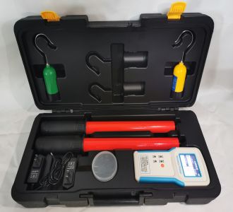
Transformer Characteristic Tester
The Transformer Characteristic Tester (also known as a Transformer Comprehensive Tester, CT/PT Characteristic Tester) is the core equipment for substation handover acceptance, preventive testing, and transformer factory calibration. It is mainly used to test the full-parameter items of current transformers (CT) and voltage transformers (PT), including volt-ampere characteristics, transformation ratio, polarity, error curve, angular difference and ratio difference, secondary load, demagnetization, etc. It is an essential multifunctional on-site test instrument for the relay protection profession.
Core Working Principle and Technical Route
Technical Route Principle Advantages Applicable Scenarios
Power-frequency voltage boosting method (traditional) Direct power-frequency voltage boosting for volt-ampere characteristics Intuitive principle Low voltage levels, simple acceptance
Variable-frequency/low-frequency method (mainstream) Lower the test frequency, low-voltage output equivalent to high knee-point voltage Lightweight equipment, high safety, strong anti-interference 220kV and above substations, TP-class transient CT testing
The variable-frequency method is currently the preferred solution for infrastructure construction and substation renovation. It only needs to output 180V AC voltage and 12A current to handle CT testing with a knee point as high as 60kV.
Selection Core: Match according to voltage level and testing requirements
1. Output capability (the most critical indicator)
Application Scenario Recommended Output Voltage Recommended Output Current Description
10kV~35kV distribution CT/PT 0~1000V 0~15A (excitation) / 0~600A (ratio) Basic model can meet the requirement
110kV~220kV main transformer CT 0~1000V (variable-frequency equivalent) 0~15A (excitation) / 0~600A (ratio) Variable-frequency technology required
500kV and above/bushing CT 0~2500V and above 0~20A (excitation) / 0~1000A (ratio) High-end model or external voltage booster
TP-class transient CT Must support transient parameter analysis — Must choose a model that supports TP-class testing
Class 0.5 (conventional) Daily preventive testing and handover acceptance by operation and maintenance teams
Class 0.2 (high precision) Measurement CT calibration, Class 0.2S transformer testing
Class 0.1/Class 0.05 (measurement grade) Electric power research institute arbitration, laboratory calibration, factory inspection
3. Functional coverage
Basic functions (essential): volt-ampere characteristics, transformation ratio, polarity, 5%/10% error curve, automatic demagnetization, data storage and export
Advanced functions (optional as needed):
Angular difference/ratio difference measurement: essential for measurement CT calibration
Secondary winding resistance/secondary load measurement: circuit integrity check
TP-class transient characteristic analysis: essential for 500kV and above systems, nuclear power/large power plants
Primary through-current test: secondary circuit channel status check
AC withstand voltage test: insulation strength verification
Parameter Item Conventional Model High-end Model
Excitation output voltage 0~1000V 0~2500V~6000V
Excitation output current 0~15A 0~20A (peak 36A)
Ratio test current 0~600A 0~1000A
Equivalent excitation voltage (variable frequency) — Up to 45kV~60kV
Ratio measurement range ≤25000A/5A 1~40000
Excitation accuracy ≤0.5% ≤0.2%
Ratio difference accuracy — ±0.05%~±0.1%
Angular difference accuracy — ±1′~±5′
Data storage 500~1000 sets 2000~3000 sets
Overall weight ≤22kg ≤9kg (high-end lightweight)
List of essential functions (hard procurement indicators)
Fully automatic testing: one-key completion of voltage/current boosting, curve plotting, knee-point identification, and error curve generation, eliminating manual voltage regulation and curve tracing
Automatic demagnetization: automatically eliminate residual magnetism after testing to avoid affecting the subsequent operation of the transformer
CT secondary side open-circuit protection: idle secondary windings must be short-circuited, and the instrument must have open-circuit alarm
Overvoltage/overcurrent protection: strictly set protection upper limits to prevent transformer damage
Data export and report generation: support USB flash drive transfer, USB/RS232 communication, and PC software for generating Word reports
On-site printing: built-in micro printer for direct on-site printing of curves and data
Compatibility with multiple wiring methods: except for load testing, other items use the same wiring method, reducing on-site wiring workload
Local and mainstream manufacturer resources
Based on past selection experience, Jiangsu (especially the Yangzhou Baoying area) is a core industrial belt for domestic power testing instruments and electric heating equipment. The transformer characteristic tester field also gathers a large number of manufacturers. When purchasing, prioritize local industrial belts, which have significant advantages in after-sales response and logistics costs.
The product line covers comprehensively, including TZHGC-E (0~1000V/20A peak), TPHGC-F (0~2500V/20A peak), and TP_HDBH3000 (12.5-inch color screen, Windows system, supports TP-class transient CT analysis, equivalent excitation voltage 45kV), covering everything from basic operation and maintenance to high-end electric power research institute applications.
Yangzhou Jinli Electric Co., Ltd.: CTP-1000 variable-frequency transformer comprehensive tester, variable-frequency technical route, lightweight design.
Yangzhou Kaier Electric Co., Ltd.: KEHGQ-Ⅰ transformer characteristic comprehensive tester, supports full-item CT/PT testing, stores 3000 sets of data, outstanding cost performance.
Yangzhou Su'er Electric Co., Ltd. (Baoying Liubao Industrial Park): SEHG-QX fully automatic transformer comprehensive tester, 0~1000V/15A output, 600A ratio current, rotary encoder operation.
Baoying County Yonggao Electric Power Equipment Manufacturing Plant: YGHGD transformer characteristic comprehensive tester, supports 220V/380V automatic identification, output up to 2000V with 380V input.
Yangzhou Wanbao Electric Power Equipment Co., Ltd.: WB-FA10 transformer volt-ampere characteristic tester, overall weight 11.2kg, built-in 12Ah lithium battery, can continuously complete 15 sets of 110kV CT testing on a single charge, suitable for high-frequency mobile operations in county-level power supply stations.
Wuhan industrial belt manufacturers (core production area for power testing instruments)
Wuhan Zhizhuo Measurement and Control Technology: ZC-203B/CTP-1000B series, variable-frequency technology, output 180V/12A can handle 60kV knee-point CT, supports TP-class transient CT analysis, ratio difference accuracy ±0.1%, widely used in pre-test teams of prefecture-level power supply companies.
Wuhan Qianxu Electric Power: QXF series variable-frequency transformer comprehensive tester, double-layer shielding against strong electromagnetic interference, suitable for on-site testing in 500kV dense busbar substations.
Wuhan Fanglin Electric Power: GDHG series, measurement-grade high precision, ratio difference accuracy up to 0.05%, suitable for full error point detection of measurement CT, widely used in electric power research institutes/measurement centers.
Executive Standards
GB 1208 / IEC 60044-1: Current transformers
GB 1207 / IEC 60044-2: Voltage transformers
GB 16847 / IEC 60044-6: Transient characteristics of current transformers for protection
DL/T 596-2021: Preventive test code for electric power equipment
DL/T 846.10: Technical guidelines for on-site testing of transformers
JJG 1021-2007: Verification regulation of power transformers
Precautions for Use
The shell must be reliably grounded. The power output terminals carry high voltage. Do not plug or unplug test leads while energized.
Idle CT secondary windings must be short-circuited. CT secondary open circuit is strictly prohibited (high voltage danger).
Strictly set the voltage/current protection upper limits to prevent transformer damage from overvoltage and overcurrent.
Before DC resistance testing, first zero-calibrate to eliminate measurement deviation caused by lead resistance.
After testing, confirm that demagnetization is complete before disconnecting wires.