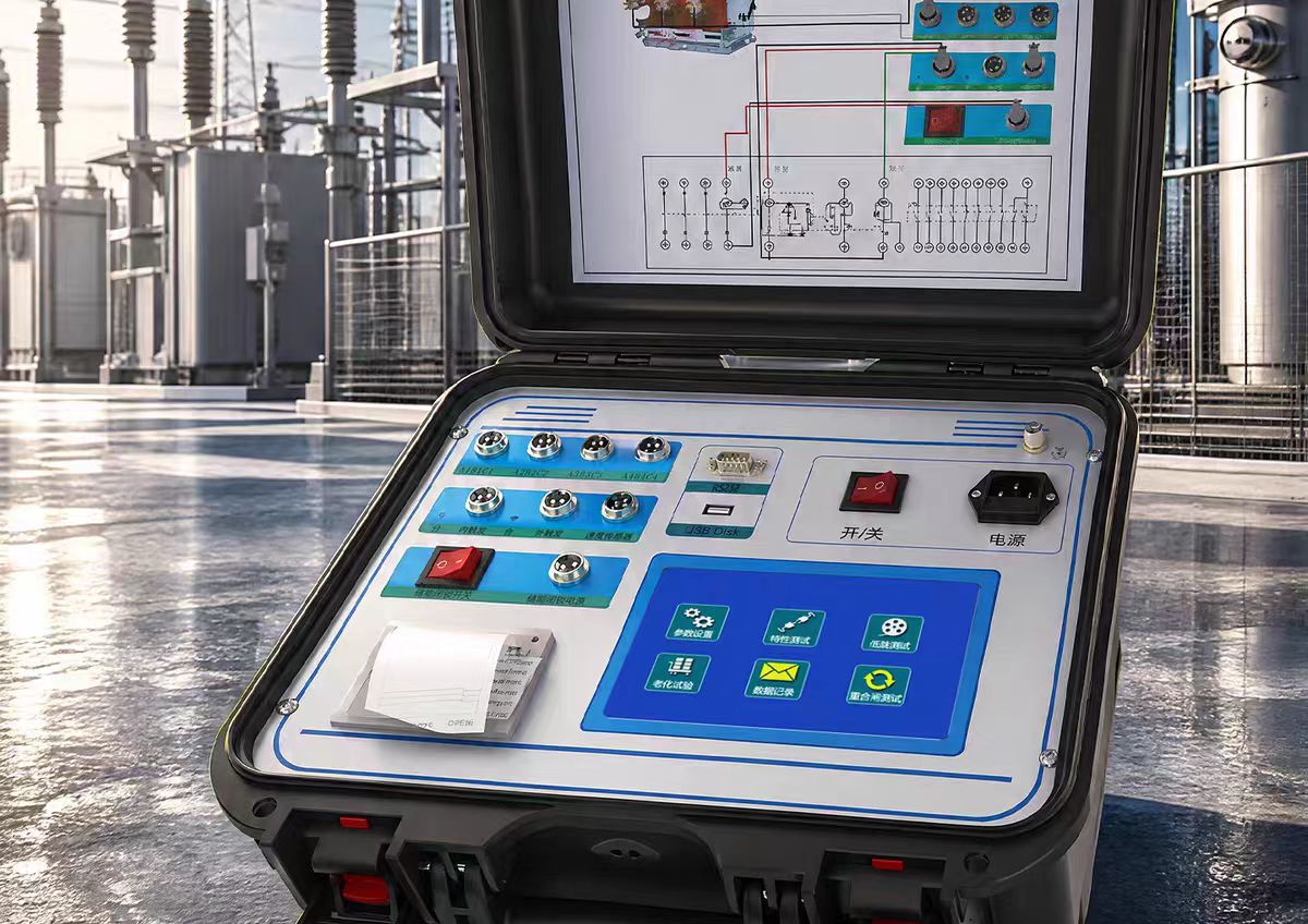

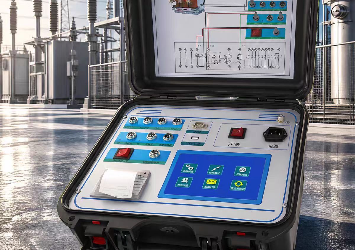
Dielectric Loss Tester
The dielectric loss tester (abbreviated as "tandelta meter") is a specialized instrument used for precise measurement of insulation performance of high-voltage electrical equipment under power-frequency high-voltage environments. By measuring two key parameters, the dielectric loss factor (tan delta) and capacitance (Cx), it enables non-destructive diagnosis of the insulation condition of transformers, instrument transformers, bushings, cables, and other equipment. It is an indispensable core tool in preventive tests of power systems.
Core Measurement Parameters
The core task of the dielectric loss tester is to precisely measure two key parameters:
Dielectric Loss Factor (tan delta): A dimensionless ratio characterizing the degree of energy loss of insulating materials in an alternating electric field, equal to the ratio of active power to reactive power (tan delta = P/Q). Pure and dry insulating materials have very small tan delta values. When insulation is damp, aged, cracked, or contains impurities, tan delta increases significantly, making it a sensitive indicator for judging insulation deterioration.
Capacitance (Cx): Reflects the overall structural condition of the insulating equipment. After moisture absorption, the capacitance value usually increases, while aging and drying cause it to decrease; for capacitive equipment (such as CVTs and bushings), significant changes in capacitance may indicate internal component breakdown, short circuit, or open circuit.
In simple terms, the dielectric loss tester uses "tan delta" to assess the quality of insulating materials and "Cx" to assess the condition of the insulation structure.
Working Principle
Modern dielectric loss testers mainly adopt the vector calculation method: a high-precision signal source inside the instrument generates a sinusoidal test voltage, which is applied to the test object and a standard capacitor. By synchronously acquiring two current signals and using digital signal processing (DSP) and discrete fast Fourier transform (FFT) techniques, the amplitude and phase difference are calculated, thereby obtaining the capacitance value (Cx) and the tangent of the dielectric loss angle (tan delta).
To cope with strong electromagnetic interference at sites such as substations, the instruments commonly adopt frequency conversion anti-interference technology—outputting an off-frequency sine wave of 45Hz/55Hz (or 40~70Hz) to automatically filter out 50Hz power-frequency interference, ensuring accurate data acquisition even in strong electric field environments.
Key Technical Parameters
Table
Download as Table
Export as Image
Parameter Typical Range
Output Voltage 0.5kV ~ 10kV, adjustable in multiple steps
Output Power 0.6kVA ~ 1.5kVA
tan delta Measurement Range 0.1% ~ 50%
tan delta Accuracy ±(Reading × 1% + 0.04%)
Capacitance Range 3pF ~ 60000pF (internal connection), ≤10μF (external connection)
Capacitance Accuracy ±(Reading × 1% + 5pF)
Resolution tan delta: 0.01%, Cx: 1pF
Power Supply AC 220V±10%, 50Hz±1Hz
Operating Temperature -15℃ ~ 50℃
Relative Humidity <90%
Weight Approximately 18kg ~ 30kg
Test Modes
The dielectric loss tester supports multiple wiring methods to adapt to equipment with different grounding conditions:
Normal Connection Method: Suitable for test objects insulated from ground (such as standard capacitors and insulating material samples in laboratories)
Reverse Connection Method: Suitable for test objects with one end directly grounded (such as transformers and instrument transformers in field operation)
External Connection Method: External standard capacitor and voltage regulator are used for large-capacity test objects or special testing requirements
CVT Self-Excitation Method: Specially used for capacitive voltage transformers; with a single connection, the capacitance and tan delta of C1 and C2 can be measured simultaneously without an external high-voltage source
Reverse Connection Low-Voltage Shielding: When the CVT busbar is grounded, 10kV reverse connection dielectric loss measurement of C11 can be performed without disassembling the wiring
Safety Protection Mechanisms
Grounding Detection: Voltage boost is locked when not reliably grounded to prevent electric shock
Overcurrent/Short Circuit Protection: Automatically cuts off high voltage when the test object breaks down or short-circuits
Overvoltage Protection: Prevents output voltage from exceeding the set value
Electric Shock Protection: Immediately cuts off high voltage in case of accidental electric shock to the operator
Anti-"Capacitive Rise" Effect: Automatically tracks output voltage to avoid voltage rise on capacitive loads
Typical Application Scenarios
Power Transformers: Measure dielectric loss and capacitance between windings and between windings and ground to evaluate the condition of transformer oil and overall insulation
Capacitive Voltage Transformers (CVTs): Use self-excitation method to measure tan delta and capacitance of C1 and C2 in one test, and can also test the transformation ratio
High-Voltage Bushings: Measure dielectric loss between the core rod and the last screen to determine whether it is damp or aged
Current/Voltage Transformers: For capacitive CTs, measure dielectric loss from primary to the last screen
Power Cables: Measure dielectric loss between the core wire and the shielding layer to assess insulation aging
Insulating Oil: Use a dedicated oil test cell to measure the dielectric loss factor of the oil to determine the degree of oil deterioration
Generators: Measure stator winding insulation loss
Surge Arresters: Measure insulation resistance and dielectric loss under weak current
Core Value
The significance of the dielectric loss tester goes far beyond the measurement readings; its deeper value lies in:
Preventive Testing: Conduct regular tests and establish data archives, compare the trends of tan delta and Cx longitudinally. Even if the values do not exceed the limits, a clear increasing trend can provide early warning
Fault Diagnosis: Provide precise quantitative analysis for suspected faulty equipment, determine the cause and severity of insulation deterioration
Condition-Based Maintenance: Shift from "periodic maintenance" to "condition-based maintenance", scientifically evaluate the insulation aging rate, and predict remaining life
Quality Acceptance: Commissioning tests after new equipment is stored and installed to ensure good operating condition
Executive Standards
GB/T 20833.3-2018: Standard for Measurement of Dielectric Loss Factor
GB/T 5654-2007: Measurement of relative permittivity, dielectric dissipation factor and d.c. resistivity of insulating liquids
GB/T 31838 series: Dielectric and resistive properties of solid insulating materials
DL/T 962-2005: Technical conditions for high voltage dielectric loss testers