

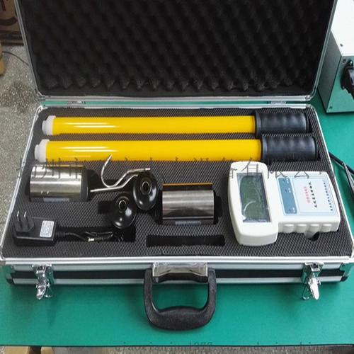
Dielectric Loss Tester
The dielectric loss tester (also known as a dielectric loss meter or anti-interference dielectric loss tester) is a precision detection instrument used in power systems to measure the dielectric loss factor (tanδ) and capacitance (Cx) of high-voltage power equipment. Its core function is to evaluate the insulation condition of transformers, bushings, instrument transformers, power cables, and other equipment, sensitively detecting defects such as overall insulation moisture, aging, oil deterioration, or partial air gap discharge. It is a core piece of equipment for preventive tests and handover tests.
I. Working Principle
Dielectric loss refers to the energy loss generated by insulating materials under an alternating electric field due to dielectric conductance and polarization lag effects. Under AC voltage, there is a phase difference between the current flowing through the dielectric and the voltage, and the tangent of the dielectric loss angle δ, tanδ, is a key parameter for measuring the degree of insulation loss.
The instrument operates based on the vector algorithm method (modern digital type) or the Schering bridge method (classical method). Modern instruments integrate a variable-frequency power supply, step-up transformer, and standard capacitor internally to generate a high-voltage sinusoidal signal with stable frequency (usually 45Hz/55Hz alternating frequency) applied to the test object. By high-speed synchronous sampling of the current signals of the standard circuit and the test circuit, through A/D conversion and digital signal processing (DSP), and using Fourier transform (FFT) for vector calculations, the tanδ and Cx values of the test object are directly calculated. The use of alternating-frequency measurement technology can effectively avoid on-site 50Hz power frequency interference and ensure accurate data.
II. Core Points for Model Selection
Measurement accuracy (primary parameter): tanδ measurement accuracy directly determines the ability to detect insulation defects. Conventional models should reach ±(1% reading + 0.0005); for 110kV and above transformer testing, high-precision models should be selected, with accuracy ≤±(0.5% reading + 0.0003) or better. Capacitance accuracy should be ≤±(1% reading + 1pF), and high resolution (≥0.1pF) can capture small capacitance changes.
Anti-interference capability (key for on-site testing): Strong power frequency electromagnetic interference exists at substation sites, so models using variable-frequency anti-interference technology must be selected (outputting pure sine waves at 45Hz/55Hz), with interference suppression ratio ≥80dB, ensuring stable data without drift under strong electric field environments. Some high-end models also have multiple anti-interference measures such as phase inversion method, phase shift method, and digital filtering.
High-voltage output capability: The output voltage levels should cover multiple adjustable levels from 0.5kV to 10kV, meeting the test voltage requirements of different types of equipment (10kV and above transformer windings usually select 10kV, bushings/tap usually select 2kV~3kV). Output current ≥20mA, ensuring that data is not distorted when testing large-capacitance test objects; voltage output amplitude accuracy ≤±1%, ripple coefficient ≤0.5%.
Test modes and applicability:
Positive connection method: measures test objects insulated to ground (such as capacitors, insulating bushings)
Reverse connection method: measures test objects grounded at one end (such as transformer windings, high-voltage cables)
CVT self-excitation method: measures capacitive voltage transformers without disconnecting high-voltage leads, completing synchronous C1/C2 measurement with one wiring setup
External connection method: supports external standard capacitors or externally applied high voltage, expanding the test range
Range: The tanδ measurement range should cover 0~100% (or 0~999%), suitable for the full-range testing of new equipment (tanδ≤0.5%) and aged equipment; the capacitance range should cover 3pF~60000pF (internal) or wider (external), covering test objects of different capacities such as bushings and cables.
Safety and intelligence: Equipped with overvoltage/overcurrent/short-circuit protection, grounding detection (voltage step-up locked if not grounded), prevention of the "capacitance rise" effect, emergency stop button; supports data storage (≥100 groups), USB/Bluetooth export, on-site printing, automatic temperature correction, and other functions.
III. Usage Method (Taking Power Equipment Testing as an Example)
Pre-test preparation: Confirm that the test equipment has been de-energized, voltage-tested, fully discharged, and reliably grounded; ambient temperature ≥+5℃, humidity ≤80%; clean the surface of the test object, measure and record insulation resistance; turn on the instrument and preheat for 15~30 minutes.
Wiring and parameter settings:
The instrument grounding terminal must be reliably grounded (scrape off paint and rust at the grounding point to ensure zero-resistance grounding)
Select positive or reverse connection method according to the grounding condition of the test object; select self-excitation method for CVT testing
Set the test voltage (10kV for 10kV and above equipment, 2kV~3kV for bushings/tap), frequency (select variable-frequency mode when interference is strong)
Test execution: After confirming correct wiring and evacuation of personnel from the high-voltage area, start the test; the instrument automatically steps up voltage and measures, displaying tanδ and Cx values after about 30~60 seconds; if data is abnormal during the test, reduce voltage and retest or switch to alternating-frequency mode.
Post-test recovery: First reduce voltage and shut down, fully discharge the test object with a discharge rod (for large-capacitance equipment, discharge at least 3 times); disconnect wires in the order of "first disconnect high-voltage line, then disconnect grounding line"; convert measurement results to the standard temperature of 20℃ and compare with historical data.
IV. Common Troubleshooting
Fault phenomenon Possible cause Troubleshooting method
Severe data fluctuation/jumping Poor hook contact, excessive grounding resistance, strong environmental interference Clean contact surfaces and secure test lines; scrape grounding point to ensure zero-resistance grounding; enable variable-frequency anti-interference mode
Negative dielectric loss value Direct measurement of CVT lower capacitor, damp electromagnetic PT, excessive humidity Use self-excitation method for CVT; dry PT porcelain bushing and terminal board; control environmental humidity or add shielding ring
Large measurement error Hidden break in test line, wrong working mode selection, standard capacitor plug not fully shielded Check test line continuity; confirm correct wiring mode; use fully shielded plug to connect standard capacitor
Instrument protection/unable to step up voltage Poor grounding, short circuit in test object, abnormal input voltage Check grounding; investigate whether test object is short-circuited; check 220V power supply voltage
Screen displays "electrode cup short circuit" Oil cup inner and outer electrodes not properly installed, impurities between electrodes Realign and fix inner electrode; thoroughly clean electrode cup
V. Usage Precautions
Strictly prohibit live operation: Must confirm that the equipment is de-energized throughout the process, and fully discharge before testing
Grounding specifications: The instrument and the low-voltage side of the test object must be reliably grounded, and the grounding point must have paint and rust scraped off
Wiring specifications: Keep high-voltage test lines away from the human body and low-voltage lines; in reverse connection method, use the core wire for the high-voltage line and leave the shielding wire suspended; when using self-excitation method for CVT, non-dedicated high-voltage lines should be lifted and suspended
Environmental requirements: Avoid working in thunderstorms and strong winds; data may be abnormal when humidity is too high, and a shielding ring may be added if necessary
Generator power supply: Use "fixed frequency 50Hz" mode when frequency is unstable
Maintenance: Regularly verify instrument accuracy with a standard capacitor; avoid damaging test lines; energize once a month during long-term non-use to prevent moisture
As a core tool for insulation diagnosis, the dielectric loss tester requires comprehensive consideration of five dimensions during model selection: measurement accuracy, anti-interference capability, high-voltage output, test mode, and range. If you have specific application scenarios (such as voltage level, equipment type, whether CVT testing is required), I can help you further refine the selection recommendations.