
High-Voltage Wireless Phase Verification Instrument
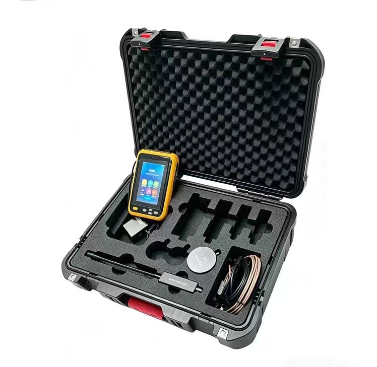
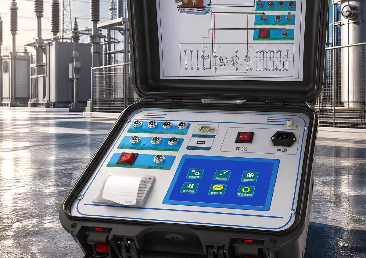
The high-voltage wireless phase verification instrument (also known as wireless phase verifier, voice phase verifier) is a specialized safety device used for phase verification and phase sequence verification in high-voltage power lines and substations. Its core function is to determine whether the power sources on both sides of a circuit breaker are in phase before two lines are connected in parallel or a loop network is closed, preventing short-circuit accidents caused by phase inconsistency.
Working Principle
The high-voltage wireless phase verification instrument consists of two detectors (transmitters) and a receiving host. The working process is as follows:
Signal Acquisition: The detector obtains voltage signals from live conductors through high-voltage capacitive voltage division or electric field induction principles. For bare conductors of 35kV and below, contact-type phase verification can be used; for bare conductors above 35kV, non-contact phase verification is adopted (gradually approach the detector to the conductor, and the induced electric field signal is sufficient).
Wireless Transmission: The detector sends phase information with precise timestamps to the receiving host via wireless means (315MHz/433MHz).
Phase Comparison: After receiving the two signals, the host aligns the waveforms based on timestamps, calculates the phase difference angle between the two voltage signals, and automatically determines whether they are in phase or out of phase.
Result Output: Typically, a phase difference of ≤15°20° is judged as in phase, and a phase difference of >30° is judged as out of phase. The phase angle and vector diagram are displayed on the LCD screen, accompanied by voice broadcast.
For remote phase verification, some high-end models adopt GPS/BeiDou satellite timing technology, where each detector is synchronized with UTC time (with errors at the microsecond to nanosecond level), enabling precise phase difference measurement within a range of hundreds of kilometers.
Main Functions
Phase Verification: Determines whether two lines are in phase; this is the core function.
Voltage Detection: Detects whether the line is live; can also be used as a high-voltage electroscope.
Phase Sequence Test: Determines positive or negative phase sequence.
Frequency Measurement: Displays line frequency (45Hz65.0Hz range).
Quantitative Phase Angle Measurement: Displays the precise phase difference angle and vector diagram of the two signals.
Voltage Level Display: Some models can display the voltage level of the tested line.
Core Technical Parameters
Table
Download as Table
Export as Image
Parameter Item Typical Indicator Description
Phase Verification Voltage Range 10V550kV Covers the full range from low voltage to ultra-high voltage
Phase Difference Accuracy ≤±5°±10° Accuracy varies by model
Frequency Accuracy ±0.1Hz±2Hz Depends on model
Wireless Transmission Distance 100m1600m In open areas; some models can penetrate walls
Remote Phase Verification Distance 0.3km800km Requires GPS timing support
Insulating Rod Length Approximately 600mm when retracted, approximately 3200mm when extended Voltage withstand level must match operating voltage
High-Voltage Leakage Current <10μA Ensures operator safety
Data Storage 999999 groups Supports USB export
Operating Temperature -35℃+50℃ Adapts to harsh outdoor environments
Main Application Scenarios
Line Parallel Connection: Before a new line is connected to the grid, verify whether the phase of power sources on both sides is consistent.
Loop Network Closure: Phase verification of power sources on both sides of the circuit breaker at the closure point of loop or dual-power grids.
Substation Phase Verification: Verify the phase relationship on each side before transformer commissioning.
Phase Sequence Verification: Confirm whether the phase sequence of busbars and cable connections is correct.
Phase Verification in Switchgear: Perform six-phase synchronization detection inside switchgear cabinets.
Routine Maintenance: Phase confirmation after line modifications or fault recovery.
Selection Key Points
Voltage Adaptation Range: Confirm coverage of actual operating voltage levels; prioritize models with "voltage adaptive identification" function to avoid low-voltage measurement distortion or high-voltage signal interruption.
Phase Difference Accuracy: Request third-party test reports from manufacturers; the core parameter phase difference accuracy should be ≤5°, and frequency accuracy ±0.1Hz.
Wireless Transmission Stability: Verify transmission distance and signal stability in the field to avoid exaggerated specifications. In strong electromagnetic interference environments such as substations, confirm the equipment's anti-interference capability.
Insulation Safety Configuration: The material and length of the insulating rod must meet standards, and the voltage withstand level must match the highest operating voltage; it should have high-voltage detection and voice prompt functions to reduce the safety risk of looking down at the screen.
Phase Verification Method: For 35kV and below, contact-type can be used; for above 35kV, non-contact phase verification must be supported to ensure operators maintain a safe distance from live parts.
Remote Phase Verification Needs: If cross-station or cross-regional phase verification is required, remote models supporting GPS/BeiDou timing must be selected.
Applicable Standards
DL/T 971-2017 "Portable Phase Verifiers for Live Working - AC 1kV to 35kV"
DL/T 408-1991 "Safety Regulations for Electric Power Work"
GB/T 1029-2005 "Test Methods for Three-Phase Synchronous Machines"
GB 311.1-2012 "Insulation Coordination"
GB 13398-2008 "Hollow insulating tubes, foam-filled insulating tubes and solid insulating rods for live working"
Usage Precautions
Before operation, confirm the live status of the tested line; perform voltage detection first, then phase verification.
Operators must operate in accordance with the high-voltage safety distance standards of the power department and wear insulating protective equipment.
Before using the insulating rod, check for cracks or moisture on the surface, and conduct regular voltage withstand tests.
In low-temperature or high-altitude environments, battery life may be affected; charge fully in advance and carry spare batteries.
Wireless communication may experience signal attenuation in dense buildings or strong interference areas; it is recommended to keep traditional wired phase verification methods as a backup.