

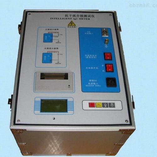
Insulation Resistance Tester
Insulation resistance tester, also commonly known as digital megohmmeter, insulation meter, or digital megger in the industry, is a core tool used in fields such as electric power, mechanical and electrical installation, and maintenance to evaluate the insulation performance of electrical equipment and ensure electrical safety. It applies a known DC high voltage to the device under test, measures the tiny leakage current generated, and calculates the insulation resistance value, which is equivalent to conducting an "insulation health check" for the equipment.
Core Working Principle
The internal circuit of the tester generates a stable DC high voltage (such as 500V, 1000V, 2500V, etc.) and applies it between the conductor and the equipment enclosure (or ground). At this time, the current flowing through the insulator is not a single component but consists of three parts:
Capacitive current: Generated by the capacitance effect of the insulator, it is relatively large at the initial stage of testing but decays rapidly to near zero within a few seconds to a dozen seconds.
Absorption current: Generated by the rearrangement of molecules inside the insulating material under the influence of the electric field, it decays more slowly and usually takes 1 minute or more to stabilize.
Leakage current: The current that actually flows through the interior or surface of the insulator, and its magnitude directly reflects the quality of the insulating material.
A professional insulation resistance tester will wait for these interference currents to decay, and after the reading stabilizes (usually recommended to wait about 1 minute), the displayed value represents the true insulation resistance. For large equipment, the instrument can also automatically calculate the Dielectric Absorption Ratio (DAR) and Polarization Index (PI) to more accurately determine whether the insulation is damp or aged.
Main Application Scenarios
Insulation resistance testers are essential tools for preventive maintenance of electrical equipment and are widely used in:
Power equipment: Transformers, generators, high-voltage motors, power cables, instrument transformers, surge arresters, etc.
Industrial sites: Inspection of insulation status of factory distribution cabinets, switchgear, and control circuits.
Product manufacturing and quality inspection: Insulation testing of power cords and enclosures for household appliances (such as rice cookers, washing machines), lighting fixtures, IT equipment, medical devices, etc., to ensure compliance with national safety standards (such as GB 4706.1, GB 7000.1, etc.).
R&D verification: Reliability testing of insulation layers during the R&D phase of electrical products.
Key Selection Indicators
Facing the many products on the market, from handheld to high-voltage types, the following indicators should be focused on when selecting:
Table
Download as Table
Export as Image
Indicator Description Selection Suggestion
Test Voltage The DC high voltage levels the equipment can output Choose based on the rated voltage of the device under test. For low-voltage equipment, choose 500V/1000V; for medium-voltage equipment, choose 2500V; for high-voltage equipment, 5kV, 10kV, or even higher is needed.
Measurement Range The maximum insulation resistance value that can be measured For ordinary equipment, 10GΩ is usually sufficient; for large transformers, long cables, etc., 100GΩ, 500GΩ, or even TΩ levels are needed.
Short-Circuit Current The maximum current that can be provided during testing The larger the current, the faster the charging of capacitive loads and the shorter the time for the reading to stabilize. For large equipment testing, it is recommended that the short-circuit current be ≥3mA.
Safety Rating The safety protection capability of the equipment Prefer products with CAT IV 600V or higher safety ratings, equipped with live detection, automatic discharge, and other functions to ensure personal safety.
Smart Functions Automation and data analysis capabilities Whether it supports automatic calculation of DAR/PI, ramp testing, data storage and download, pass/fail judgment, etc., which can greatly improve testing efficiency and accuracy.
Common Misconceptions and Safety Precautions
Misconception: A multimeter can replace an insulation resistance tester
Fact: The resistance range of a multimeter only outputs a low voltage of 3-12V, which cannot simulate the actual working conditions of equipment under hundreds or thousands of volts, and the measurement range usually does not exceed 20MΩ, making it unable to detect insulation micro-cracks, moisture, or aging issues that are only exposed under high voltage. Using a multimeter to measure insulation is a typical violation of regulations and can bury serious accident hazards.
Misconception: High-voltage testing will break down normal equipment
Fact: Insulation resistance testing is a non-destructive test. The standard test voltage is far lower than the equipment's withstand voltage test voltage, and the output current is at the microampere/nanoampere level with extremely low energy. Its purpose is precisely to screen out risky insulation before the equipment is energized and operated, avoiding accidents such as short circuits and fires during operation.
Safety Operation Iron Rules
Power off and verify: Before testing, ensure that the device under test is completely powered off and verify with a multimeter that there is no voltage.
Correct wiring: Follow the principle of "L" for conductor, "E" for ground, and "G" for guard terminal to eliminate interference from surface leakage current.
Full discharge: After testing, wait for the instrument to automatically discharge or manually discharge to ground, and confirm that there is no residual high voltage before disconnecting wires.