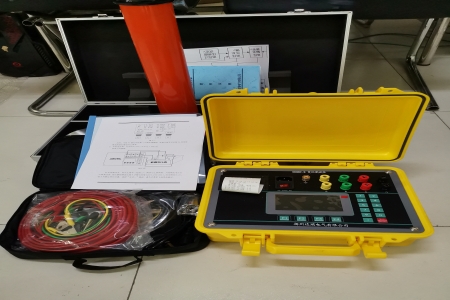

Insulation Resistance Tester
An insulation resistance tester (also known as a megohmmeter, shake table, or high resistance meter) is a professional instrument used to detect the insulation performance of electrical equipment, widely applied in fields such as electric power, industry, electronic manufacturing, and scientific research.
Working Principle
Based on Ohm's law (R = V / I), it applies a known DC high voltage to the object under test, measures the resulting weak leakage current, and thereby calculates the insulation resistance value.
Core Structure
High-voltage generator: generates the DC high voltage required for testing (traditional shake tables use hand-cranked generators, while modern digital types use DC voltage converters)
Measurement circuit: detects weak leakage current and calculates resistance value
Display device: analog pointer or digital LCD display
Terminals: L (line terminal), E (earth terminal), G (guard terminal)
Main Types
Table
Download as table
Export as image
Type Features
Traditional analog shake table Powered by hand-cranked generator, simple structure, no battery required
Digital megohmmeter Built-in battery/adapter, LCD display, rich features, data storage capability
High-voltage insulation tester Test voltage up to 5kV~15kV, suitable for large power equipment
Key Technical Parameters
Test voltage levels: common options include 50V, 100V, 250V, 500V, 1000V, 2500V, 5kV, 10kV, 15kV, etc.
Measurement range: generally from 0.01MΩ to hundreds of GΩ or even TΩ levels
Short-circuit current: ≥2~8mA; the larger the short-circuit current, the faster the charging of capacitive loads and the more stable the reading
Safety rating: CAT III 1000V / CAT IV 600V, etc.
Automatic calculation functions: polarization index (PI), dielectric absorption ratio (DAR), dielectric discharge rate (DD)
Test Voltage Selection Reference
According to national standard GB50150, the test voltage should match the working voltage of the equipment under test:
Table
Download as table
Export as image
Equipment working voltage Recommended test voltage
U < 100V 100V~250V
100V ≤ U < 500V 500V
500V ≤ U < 3kV 1000V
3kV ≤ U ≤ 10kV 2500V
U > 10kV 5kV and above
Wiring Method
L terminal (line terminal): connect to the conductive part of the object under test that is insulated from earth (such as windings or conductors)
E terminal (earth terminal): connect to the housing or grounded part of the object under test
G terminal (guard terminal): connect to the protective shielding part to eliminate errors caused by surface leakage current
For example, when measuring the insulation of a three-phase motor: connect one test lead to the motor winding and the other to the motor housing.
Reading Explanation
After the test starts, the reading usually gradually rises and stabilizes because the insulator exhibits three current effects:
Capacitive current: charges the "capacitance" of the insulator in the initial stage, tending to zero after a few seconds to a dozen seconds
Absorption current: the dielectric material molecules rearrange and absorb electrical energy, generally lasting for 1 minute or longer
Leakage current: the true insulation leakage, which is key to judging insulation quality
Generally, it is necessary to wait about 1 minute for a relatively accurate reading.
Common Brands and Models
Table
Download as table
Export as image
Brand Representative model Test voltage Measurement range
Fluke 1508 50~1000V 0.01MΩ~10GΩ
Fluke 1535/1537 250~2500V Up to 500GΩ
Fluke 1555 Up to 10kV Up to 2TΩ
Megger S1-568/1068/1568 5kV/10kV/15kV Up to 35TΩ
Usage Precautions
Strictly prohibit testing while energized; before testing, confirm that the equipment under test is de-energized and discharged
After testing, the instrument will automatically discharge, but still wait for the discharge to complete before touching the object under test
After long-term storage, check battery level before use
In humid environments, pay attention to the use of the G terminal guard wire to eliminate surface leakage errors
Fluctuating readings are normal; wait for stabilization before recording
Combined with your previous knowledge of sheathed electric heaters and tubular electric heaters, the insulation resistance tester is exactly suitable for detecting the insulation performance of these heating elements—testing whether the insulation resistance between the heating wire and the sheath tube meets standards, and determining if there are issues such as insulation aging or moisture. If you have specific testing needs, you can tell me the voltage level and type of the equipment under test, and I can help you recommend suitable test voltage and instrument models.